
Vertically packaged switched-mode power converter

a power converter and vertically packaged technology, applied in the direction of electric variable regulation, process and machine control, instruments, etc., can solve the problems of limiting efficiency, power density and reliability, pushing the existing power conversion technology to its limit, and low efficiency, and achieve fast transient response.

Active Publication Date: 2006-03-14
MYPAQ HLDG LTD
View PDF13 Cites 128 Cited by
  • Summary
  • Abstract
  • Description
  • Claims
  • Application Information

AI Technical Summary

Benefits of technology

"The present invention provides a package design for a power converter that addresses the need for multiple, low supply voltages with tight regulation and fast transient responses. The vertical package design incorporates a magnetic core and winding arrangement that allow power to flow vertically from an input module to an output module. This design reduces losses and parasitics, and the use of a matrix integrated magnetics (MIM) core creates a cellular structure that can provide multiple output voltages and faster transient response. The MIM core can be positioned in different ways, such as through holes in a PCB or extending laterally outside the core window and then turned vertically. The technical effects of this invention include improved efficiency, tight regulation, and fast transient responses."

Problems solved by technology

Transformers and inductors used within these power converters may be large and bulky and often limit their efficiency, power density and reliability.
While each individual requirement represents a challenge for the power converter design and packaging, it is the combination of them all together that is pushing the existing power conversion technology to its limit.
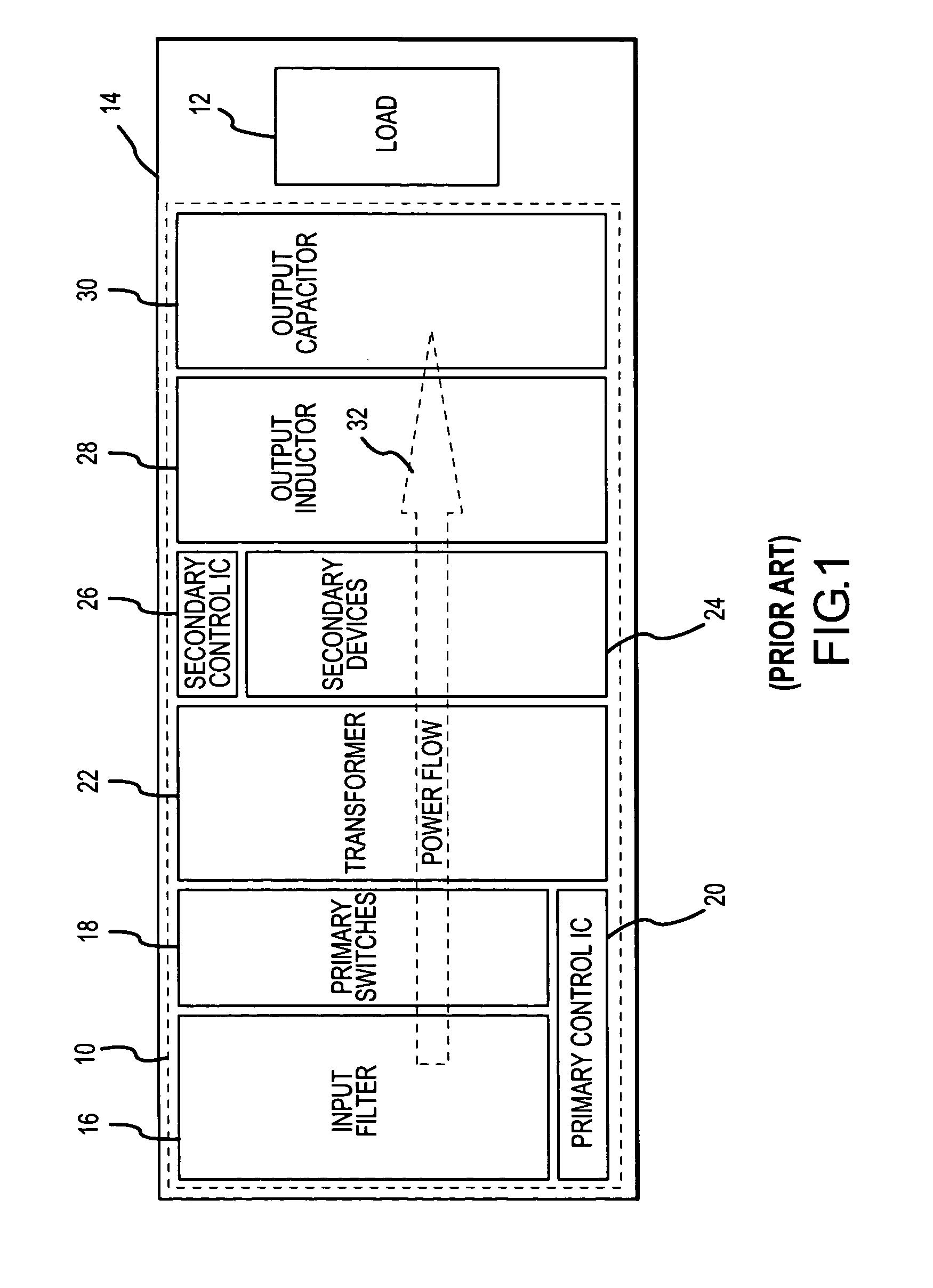
The conventional horizontal package has fundamental limitations that will render it ineffective for these developing applications, including a) inherently low efficiency, especially at sub-1V output, due to the long internal interconnects and the associated high conduction losses, b) a difficult 1-D interface with the load, c) inability to supply tightly regulated multiple outputs, and (d) switching frequency limitation due to the inductive and capacitive parasitics inherent in long interconnects.
The needs for coordination among multiple supply voltages, such as sequencing, also makes it difficult to use multiple, individually controlled single-output converters.
In addition, conventional control design focuses on constant output regulation with steady-state load, which cannot meet the future needs for dynamic voltage scaling and fast transient responses.

Method used


Image

  • Vertically packaged switched-mode power converter
  • Vertically packaged switched-mode power converter
  • Vertically packaged switched-mode power converter

Examples


Embodiment Construction

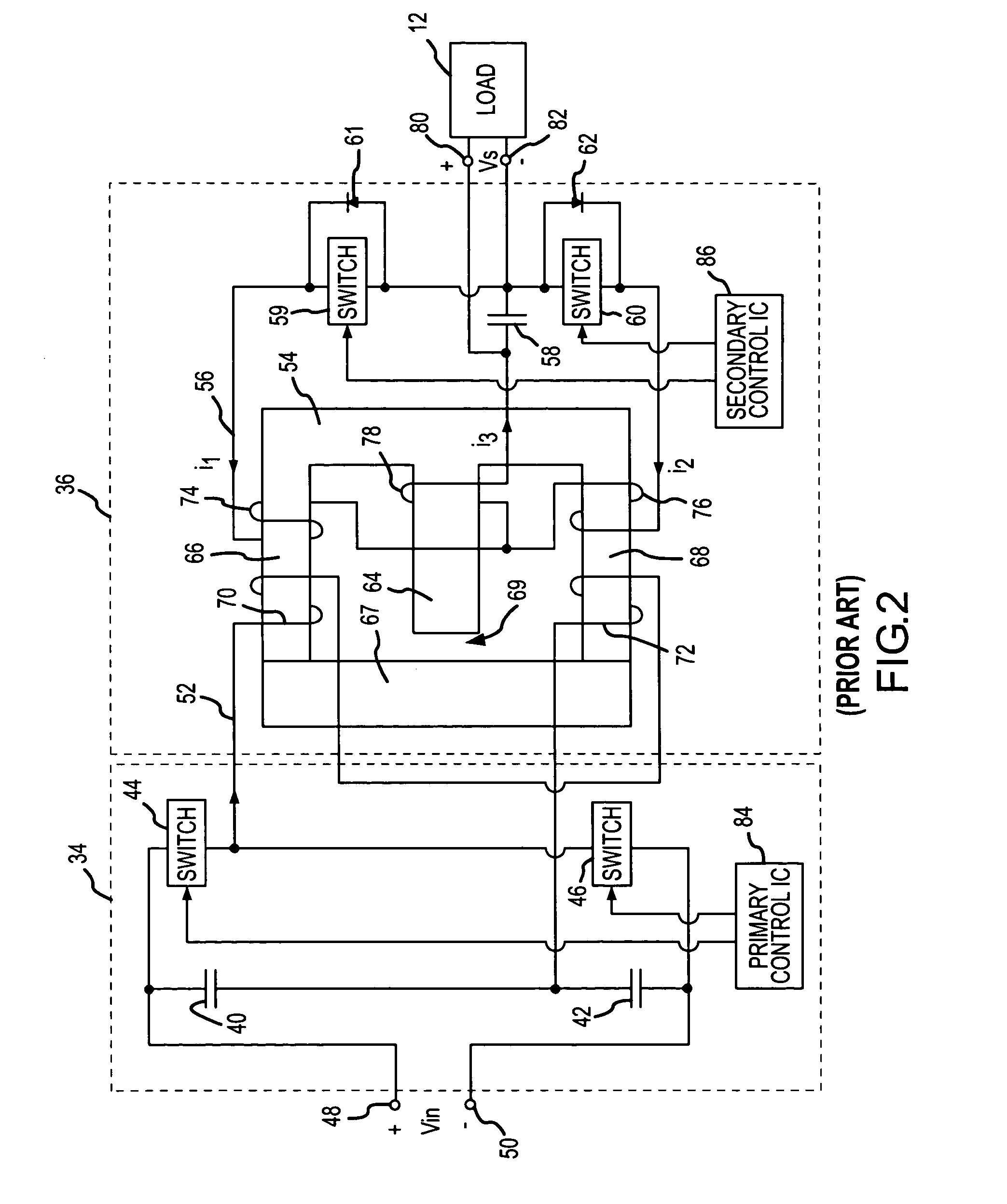
[0030]The present invention provides a package design for a power converter that addresses the need for multiple, dynamically scalable low supply voltages with tight regulation and fast transient responses. This is accomplished with a vertical package that incorporates a magnetic core and winding arrangement that allows power to flow vertically from an input module to an output module. The vertical package provides very short internal interconnects and a 2-D interface with the load, which reduce losses and parasitics. The vertical package may be implemented with vertical winding arrangements that are inherently more efficient than convention planar magnetics. The use of a matrix magnetics core creates a cellular structure that can be used to provide multiple output voltages and / or interleaving of currents to provide output voltages with very low ripple and faster transient response. The vertical package design can be implemented with both isolated and non-isolated CDR circuits as we...


PUM


Abstract

A vertically packaged cellular power converter solves the problems associated with conventional designs and paves the way for a cellular circuit architecture with ultra-low interconnect resistance and inductance. The vertical packaging results in a power flow in the vertical direction (from the bottom to the top) with very short internal interconnects, thereby minimizing the associated conduction losses and permitting high conversion efficiency at high currents. The cellular architecture is ideally suited for generating multiple supply voltages.

Description

BACKGROUND OF THE INVENTION[0001]1. Field of the Invention[0002]This invention relates to power converters and more specifically to a packaging architecture that provides for vertical power flow that is effective for providing lower supply voltages, dynamic voltage scaling, multiple supply voltages, and fast transient response and tight regulation.[0003]2. Description of the Related Art[0004]Power converters are key components in many military and commercial systems and they often govern size and performance. Power density, efficiency and reliability are key characteristics used to evaluate the characteristics of power converters. Transformers and inductors used within these power converters may be large and bulky and often limit their efficiency, power density and reliability. These deficiencies can be improved by using a high-frequency “switch-mode” architecture instead of a traditional low frequency transformer and by replacing conventional core-and-wire designs with “planar magn...

Claims


Application Information

Patent Timeline
Patent Type & Authority Patents(United States)
IPC IPC(8): G05F3/06
CPCH02M7/003H01F27/2804H05K1/144H01F2038/006
Inventor MEHROTRA, VIVEKSUN, JIANCHANDRASEKARAN, SRIRAM
Owner MYPAQ HLDG LTD
Learn More