Video monitoring system of full digitalized networking safe city

A video monitoring system, all-digital technology, applied in television systems, closed-circuit television systems, and transmission systems that adapt to optical transmission, can solve problems such as unfavorable storage device management and maintenance, scattered deployment of storage devices, and occupation of optical fiber resources. Meet the requirements of massive video data storage and management, save optical fiber and pipeline resources, and improve the effect of informatization

Inactive Publication Date: 2010-06-16
武汉市公安科学技术研究所 +1
View PDF0 Cites 46 Cited by
  • Summary
  • Abstract
  • Description
  • Claims
  • Application Information

AI Technical Summary

Problems solved by technology

This solution realizes centralized digital processing of front-end equipment, but it is difficult to achieve large-capacity deployment. Its disadvantages are:
[0003] 1. Since the front-end equipment has not been digitized, the video surveillance management platform cannot directly control the front-end equipment or detect it. Therefore, the operation and maintenance of the front-end equipment is usually done manually, which is not conducive to the deployment of large-scale monitoring points
[0004] 2. In order to ensure the video quality, the single-channel video of the video optical transceiver takes up more than 8M bandwidth, which takes up a lot of fiber resources; the transmission mode of the video optical transceiver needs an optical fiber for every 4 monitoring points on average
[0005] 3. Digital hard disk video recorder is used for storage, and the receiving equipment of video optical transceiver is deployed in the police station, so the deployment of storage equipment is too scattered, which is not conducive to the management and maintenance of storage equipment

Method used


Image

  • Video monitoring system of full digitalized networking safe city
  • Video monitoring system of full digitalized networking safe city
  • Video monitoring system of full digitalized networking safe city

Examples


Embodiment Construction

[0032] Describe in detail below in conjunction with accompanying drawing and embodiment (taking Wuhan as an example):

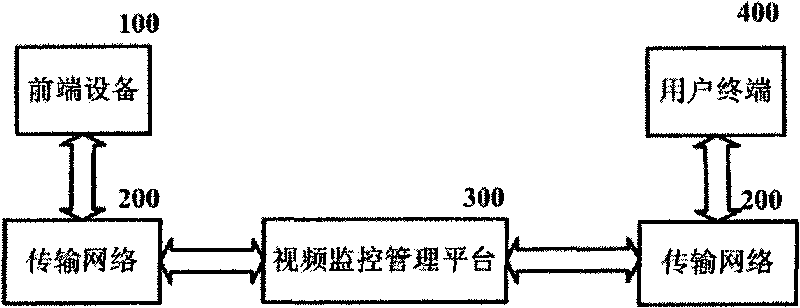
[0033] 1. Overall structure of urban video surveillance system

[0034] Such as figure 1 , the urban video monitoring system is composed of a front-end device 100, a transmission network 200, a video monitoring management platform 300 and a user terminal 400;

[0035] Its connected relationship is:

[0036] The front-end equipment 100, the transmission network 200, the video surveillance management platform 300, the transmission network 200 and the user terminal 400 are connected sequentially;

[0037] The front-end device 100 is a source of system monitoring information;

[0038] The transmission network 200 is a medium for transmitting system monitoring information;

[0039] Video surveillance management platform 300 is a platform for system resource management, sharing and application;

[0040] The user terminal 400 is an object of the system informat...


PUM


Abstract

The invention discloses a video monitoring system of a full digitalized networking safe city, and relates to a video monitoring system. The video monitoring system of the invention is composed of front-end equipment (100), a transmission network (200), a video monitoring management platform (300) and a user terminal (400), wherein the front-end equipment (100), the transmission network (200), the video monitoring management platform (300), the transmission network (200) and the user terminal (400) are communicated from back to forth in sequence; the front-end equipment (100) is the source of system monitoring information; the transmission network (200) is a medium for transmitting the system monitoring information; the video monitoring management platform (300) is a platform for system resource management, sharing and application; and the user terminal (400) is the object served by the system information. The video monitoring system of the invention realizes digital access of front-end monitory points, arranges monitory probes according to the logical relation of ring, lump, lattice and point, and is suitable for popularization in video monitoring applications in large-scale city.

Description

technical field [0001] The invention relates to a video monitoring system, in particular to an all-digital networked safe city video monitoring system. Background technique [0002] At present, in the construction plan of a safe city, the images collected by the front-end equipment are mostly transmitted to the police station through the transmission mode of the video optical transceiver, and then the digital hard disk video recorder (DVR) is used to realize the analog-to-digital conversion and then connected to the IP network. This solution realizes centralized digital processing of front-end equipment, but it is difficult to achieve large-capacity deployment. Its disadvantages are: [0003] 1. Since the front-end equipment has not been digitized, the video surveillance management platform cannot directly control the front-end equipment or detect it. Therefore, the operation and maintenance of the front-end equipment is usually done manually, which is not conducive to the d...

Claims


Application Information

Patent Timeline
Patent Type & Authority Applications(China)
IPC IPC(8): H04N7/18H04N7/22H04L29/06H04L12/46
Inventor 许汝南王炜余卫东杨裕欢贺波涛
Owner 武汉市公安科学技术研究所
Why Eureka
Try Eureka