Vacuum cleaner nozzle

A vacuum cleaner and vacuum cleaner technology, applied in the field of vacuum cleaners and low-power vacuum cleaners, can solve the problem of not being able to easily enter hidden places, and achieve the effect of fast dust removal

Inactive Publication Date: 2010-06-23
SEB SA
View PDF3 Cites 7 Cited by
  • Summary
  • Abstract
  • Description
  • Claims
  • Application Information

AI Technical Summary

Problems solved by technology

However, such a technical solution has the disadvantage of not being able to easily access concealed places or those parts that are difficult to access
However, such a solution is not particularly suitable for low-power vacuum cleaners, since on the contrary it requires a high power in order for the dust to be directed from different openings of the extractor towards the central suction duct
Furthermore, even though this solution designs brushes located at the side openings to better collect dust, this solution retains performance that can be improved

Method used


Image

  • Vacuum cleaner nozzle
  • Vacuum cleaner nozzle
  • Vacuum cleaner nozzle

Examples


Embodiment Construction

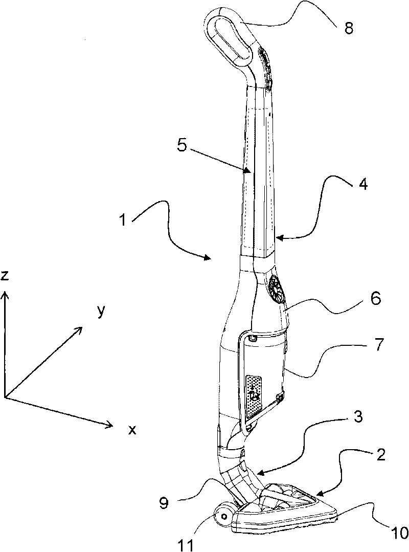
[0030] figure 1 A sweeping cleaner 1 is shown comprising a suction 2 in its lower part, which is connected to a handle 4 via an intermediate connection 3 . This handle 4 comprises a grip 8 at the upper end and forms a housing comprising: a battery 5, a motor 6 and means 7 for separating and storing waste, said housing being removable in order to be able to be cleaned. This handle 4 is articulated relative to the suction device 2 with several degrees of freedom and is directly manipulated by the user during sweeping in order to move said suction device 2 over the floor to be cleaned.

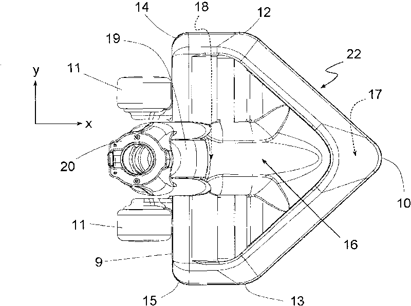
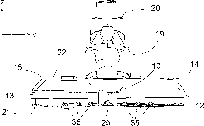
[0031] The aspirator 2 has a particular shape comprising a tip 10 for frontal orientation and a transverse edge 9 on which are mounted some wheels 11 for its advancement. For the purposes of the subsequent description, the longitudinal direction x is defined to mean the horizontal axis of symmetry of the aspirator oriented from rear to front, passing through the center of its rear edge 9 and its...


PUM


Abstract

The nozzle has a sole plate (21) comprising reliefs forming two transverse channels (37) for receiving a suction flow. The transverse channels are defined by juxtaposed transverse scraping ribs (38), where the scraping ribs are extended in a transverse direction (y) perpendicular to a displacement direction (x) of the nozzle. The scraping ribs scrap a moquette floor to facilitate suction of waste on the floor.

Description

technical field [0001] The present invention relates generally to an extractor for a vacuum cleaner, particularly suitable for use in low power vacuum cleaners such as sweeping vacuum cleaners. The vacuum cleaner, whose frame is integrated into a rigid handle that is articulated relative to the extractor and directly manipulated by the operator, is generally referred to as a sweeping vacuum cleaner. The invention also relates to such a vacuum cleaner, such as comprising an aspirator as described above. Background technique [0002] The sweeping cleaners described in documents EP1611829 and EP0909546 comprise a rigid handle articulated in several degrees of freedom relative to the extractor placed on the floor for its manipulation. The extractor naturally plays an important role in the efficient cleaning of the vacuum cleaner assembly, since it fulfills the function of removing dust and waste from the floor to be cleaned. The effect of the aspirator is particularly importan...

Claims


Application Information

Patent Timeline
Patent Type & Authority Applications(China)
IPC IPC(8): A47L9/00
CPCA47L9/0477A47L9/0488A47L5/28
Inventor 阿兰·索昂斯尔维恩·瑞纳德阿兰·奥蒙
Owner SEB SA
Why Eureka
Try Eureka