

Compression plate connecting structure of dust-connecting bucket component
A technology of connecting structure and compression plate, applied in the direction of suction filter, etc., can solve the problems of unsmooth airflow, affecting the direction of wind flow, and difficulty in aligning the combined orientation of the assembly gear shaft and the connecting shaft, so as to achieve smooth flow and reduce airflow noise. Effect
- Summary
- Abstract
- Description
- Claims
- Application Information
AI Technical Summary
Problems solved by technology
Method used
Image

Examples
Embodiment Construction
[0038] The present invention will be described in detail below with reference to the drawings and examples. The same symbols are used for the same components in the present invention as in the prior art.
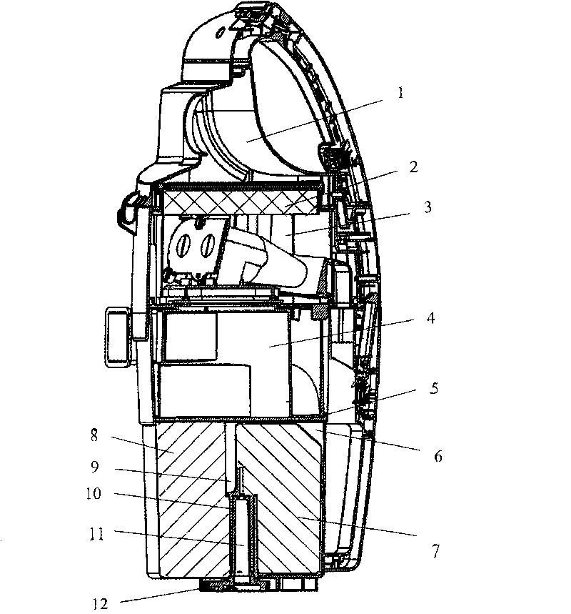
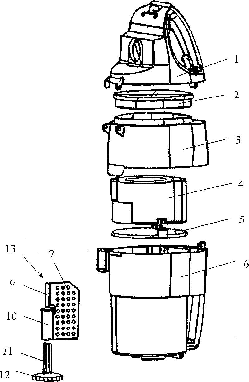
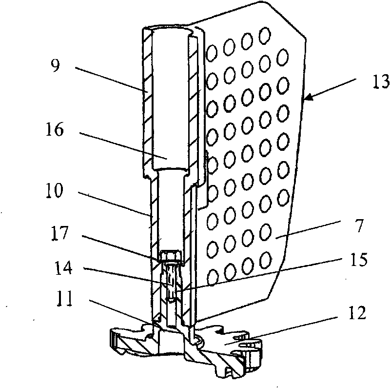
[0039] The compression plate connecting structure of the dust collecting bucket assembly of the present invention, such as Figure 4 , Figure 5 , Image 6 as shown, Figure 4 It is a three-dimensional view of the compression plate connection structure of the present invention; Figure 5 It is a partial sectional view of the connection structure of the compression plate of the present invention; Image 6 It is a three-dimensional view of the compression plate of the present invention; Figure 7 It is a three-dimensional view of the gear shaft and the gear of the present invention.
[0040] The compression plate connection structure 19 of the dust collection barrel assembly of the present invention is composed of a compression plate 7 and a column 20 affixed to one side...
PUM
 Abstract
Description
Claims
Application Information