Well wall body module

A wall and shaft wall technology, which is applied in the field of shaft wall modules with improved and optimized structures, can solve the problems of large size difference between through holes and splicing holes, templates are prone to fracture and damage, and wall strength is uneven.

Inactive Publication Date: 2010-06-23
梁林华
View PDF10 Cites 8 Cited by
  • Summary
  • Abstract
  • Description
  • Claims
  • Application Information

AI Technical Summary

Problems solved by technology

When the distance between the two ribs is too small, the formwork parts on both sides constituting the half hole are prone to breakage and damage during forming, handling and construction
In addition, when the position of the rib is inappropriate, the size of the through hole and the splicing hole is very different, resulting in the concrete or mortar poured inside the wall forming filling bodies of different sizes in the through hole and the splicing hole, resulting in uneven strength of the wall

Method used


Image

  • Well wall body module
  • Well wall body module
  • Well wall body module

Examples


Embodiment 1

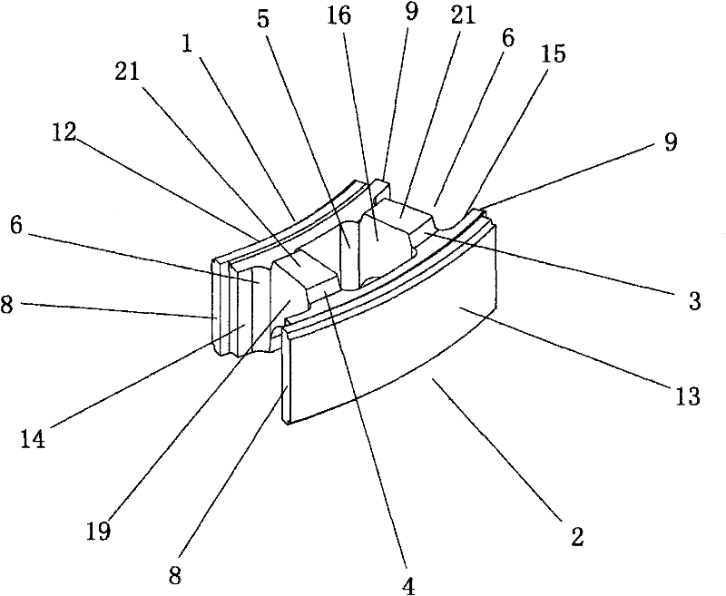
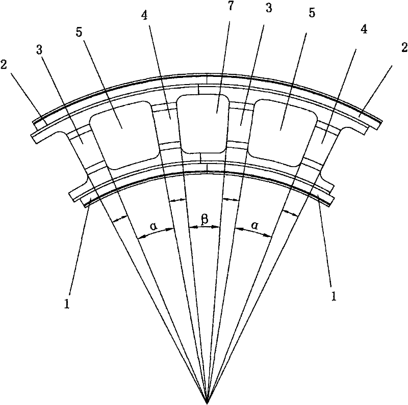
[0022] Such as figure 1 , figure 2 and image 3 As shown, the first shaft wall module of the present invention includes a front formwork 1, a rear formwork 2, a first rib 3 and a second rib 4, the front formwork 1 and the rear formwork 2 are coaxial circular arc formworks, the first The rib 3 and the second rib 4 are located between the front template 1 and the rear template 2, the first rib 3 and the second rib 4 connect the front template 1 and the rear template 2, there is a through hole 5 in the middle of the well wall module, and the well wall There are half holes 6 at both ends of the body module. When two well wall modules are connected together, the half holes 6 at the ends of the adjacent well wall modules form splicing holes 7; the two vertical surfaces of the first rib 3 The angle between the center of the circle and the angle between the two vertical surfaces of the second rib 4 are equal, that is, the angle between the center of the first inner surface 16 and t...

Embodiment 2

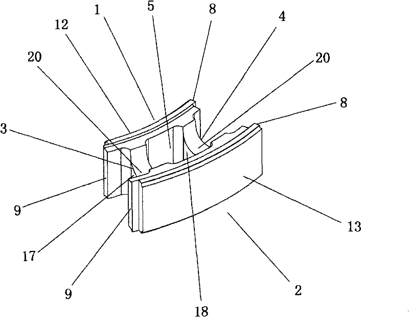
[0027] Such as Figure 4 , Figure 5 and Figure 6As shown, the second well wall module of the present invention includes a front formwork 1, a rear formwork 2, a first rib 3 and a second rib 4, the front formwork 1 and the rear formwork 2 are coaxial arc-shaped formworks, the first The rib 3 and the second rib 4 are located between the front template 1 and the rear template 2, the first rib 3 and the second rib 4 connect the front template 1 and the rear template 2, there is a through hole 5 in the middle of the well wall module, and the well wall There are half holes 6 at both ends of the body module. When two well wall modules are connected together, the half holes 6 at the ends of the adjacent well wall modules form splicing holes 7; the two vertical surfaces of the first rib 3 The angle between the center of the circle and the angle between the two vertical surfaces of the second rib 4 are equal, that is, the angle between the center of the first inner surface 16 and th...


PUM


Abstract

The invention relates to a well wall body module which comprises a circular arc-shaped front template (1), a circular arc-shaped rear template (2), a first rib (3) and a second rib (4). The front template (1) and the rear template (2) are coaxial, a through hole (5) is arranged at the middle part of the well wall body module, and semi-holes (6) are arranged at the two ends of the well wall body module. When the modules are in connection, the semi-holes (6) at the end parts of adjacent modules form spliced holes (7). Circle center included angles between the through hole (5) and the two vertical side faces of the spliced holes (7) are equal. As the dimension relationship of the modules is optimized, the parts of the front template (1) and the rear template (2) protruding out of the first rid (3) and the second rib (4) cannot be too long, thereby avoiding the templates from being cracked and damaged. When the modules are adopted to build a wall body in a seam pressing manner, the spliced holes (7) at the end parts of the adjacent modules on the same layer form pouring holes which are uniform in both shape and size with the through holes (5) at the middle parts of the adjacent modules, and concrete poured into the pouring holes form intensity components which are uniform in both shape and size in the pouring holes, thereby leading the intensity of the wall body to be uniform.

Description

technical field [0001] The invention relates to a shaft wall module, in particular, the invention relates to a shaft wall module with an improved and optimized structure. Background technique [0002] In the prior art, there are many convenient shaft wall modules for construction. Chinese patent document CN1206429C discloses a well wall module, and the national building standard design atlas "Concrete Modular Drainage Inspection Well" (atlas number is 05SS522) also discloses a well wall module. These modules include two coaxial arc-shaped templates and two ribs that are located between the aforementioned two templates and connect the aforementioned two templates. A through hole is formed between the two templates and the two ribs, and the two ribs are respectively Two half holes are formed at the ends of the two templates, and when two well wall modules are connected together, the half holes at the ends of adjacent well wall modules are connected together to form a splicing...

Claims


Application Information

Patent Timeline
Patent Type & Authority Applications(China)
IPC IPC(8): E04C1/39E02D29/12
Inventor 梁林华
Owner 梁林华
Why Eureka
Try Eureka