Brake

A technology of brakes and brake teeth, which is applied in the direction of brake types, brake components, brake actuators, etc., can solve the problems of difficult control, not so fast response time of the motor, and poor control accuracy, so as to improve the response performance Effect

Inactive Publication Date: 2010-06-23
CHERY AUTOMOBILE CO LTD
View PDF4 Cites 5 Cited by
  • Summary
  • Abstract
  • Description
  • Claims
  • Application Information

AI Technical Summary

Problems solved by technology

This kind of brake with self-locking mechanism, to release the brake, the motor must be reversed, which is allowed for the parking system with low response time requirements, but for the driving brake, it is necessary to achieve 20 to 50 brake adjustments per second , to make the

Method used


Image

  • Brake
  • Brake
  • Brake

Examples


Embodiment Construction

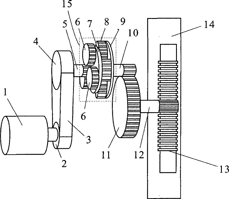
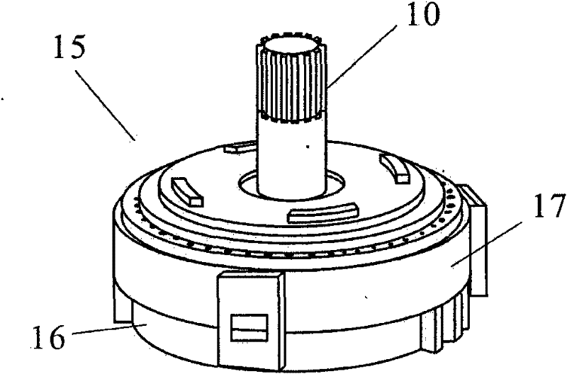
[0013] Please also refer to figure 1 with figure 2 , as shown in the figure, a brake includes a mechanical transmission mechanism and a brake rack push rod mechanism. The mechanical transmission mechanism includes a drive motor 1, a first transmission gear 2 driven by the drive motor 1, and the first transmission gear 2 The drive belt 3 engaged with the drive belt 3, the second transmission gear 4 driven by the drive belt 3; the brake rack push rod mechanism further includes the first sun gear 5 driven by the second transmission gear 4, and the first sun gear 5 is installed The connected deceleration torque increasing mechanism 15, the first reduction gear 10 protruding from the deceleration torque increasing mechanism 15, the second reduction gear 11 meshing with the first reduction gear 10, the third reduction gear driven by the second reduction gear 11 12. The gear rack 13 used for braking the brake pads 14 moves through the meshing belt; the deceleration and torque-incre...


PUM


Abstract

The invention discloses a brake, comprising a mechanical driving mechanism and a braking rack push-rod mechanism, wherein the mechanical driving mechanism comprises a drive motor, a first driving gear, a driving belt and a second driving gear; and the braking rack push-rod mechanism comprises a first sun wheel driven by the second driving gear, a speed-reduction incremental size mechanism connected with the first sun wheel, a first reducing gear extended out from the speed-reduction incremental size mechanism, a second reducing gear mutually engaged with the first reducing gear and a third reducing gear driven by the second reducing gear. The third reducing gear drives a rack acting on a brake block to move by engagement. The brake adopts the non-thread gears and a rack driving mechanism. When reaction force is larger than forward propulsion, a propulsion unit of the mechanism can realize automatic backtracking, so that brake output is regulated by controlling the size of brake output torque, the non-self-locking function is realized, and the response performance of power conditioning of the brake is improved.

Description

technical field [0001] The invention relates to a brake, in particular to a vehicle brake. Background technique [0002] At present, most vehicle brake systems at home and abroad are still based on hydraulic control of mechanical pressure to achieve the purpose of braking. The new brake-by-wire system has just started. It generates braking displacement through the pedal pressure simulator, and the output braking torque is processed by the corresponding electronic control unit. Through this technology, we can realize that the braking signal is controlled by the embedded controller. collected and processed accordingly. Among them, the performance of the brake is very important. Electric braking generally uses a motor-driven mechanical device to achieve braking. A high-power motor can be used to directly drive the mechanical device. The advantages are flexible control and short response time. The disadvantage is that it is large in size and high in cost; Use a low-power motor...

Claims


Application Information

Patent Timeline
IPC IPC(8): F16D65/21F16D65/18
Inventor 王陆林王建辉
Owner CHERY AUTOMOBILE CO LTD
Why Eureka
Try Eureka