Permanent magnet magnetorheological damper with adjustable damping force

A magnetorheological damper, permanent magnet technology, applied in the direction of vibration suppression adjustment, non-rotational vibration suppression, etc., to achieve a wide range of applications, meet the performance requirements, and easy to use

Inactive Publication Date: 2011-11-30
CHONGQING MATERIALS RES INST
View PDF6 Cites 2 Cited by
  • Summary
  • Abstract
  • Description
  • Claims
  • Application Information

AI Technical Summary

Problems solved by technology

[0002]The magneto-rheological damper is an intelligent damping device, and its damping force can be remotely adjusted steplessly by controlling the power supply. Therefore, the ordinary magneto-rheological damper The rheological damper must be equipped with a control power supply to achieve the purpose of adjusting the output damping force of the magnetorheological damper; in order to reduce the dependence of the magnetorheological damper on the control power supply, a permanent magnet magnetorheological damper has been developed. For example, the patent application number is: ZL2008200999097 for a permanent magnet adjustable magneto-rheological damper and the patent application number is: 2005100311088 for a permanent magnet adjustable assembled magnetorheological damper, although they can also work independently without a control power supply, Although its damping force can also be changed in a certain way, once this type of permanent magnet magneto-rheological damper is manufactured, its damping force cannot be continuously adjusted according to the site conditions. limits

Method used


Image

  • Permanent magnet magnetorheological damper with adjustable damping force
  • Permanent magnet magnetorheological damper with adjustable damping force
  • Permanent magnet magnetorheological damper with adjustable damping force

Examples


Embodiment Construction

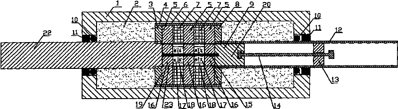
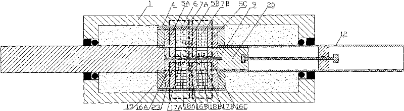
[0022] The structure of the present invention is described in detail below in conjunction with accompanying drawing:

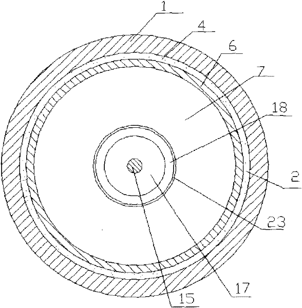
[0023] see figure 1 , which is a specific structure of the present invention, the piston 19 is made of non-magnetic metal left baffle plate 3, highly magnetic metal ring 5, non-magnetic metal ring 7 and non-magnetic metal right baffle plate 8, embedded in non-magnetic The metal tube 6 is formed; the non-magnetic metal piston rod 22 is fixed on the left baffle plate 3 through threads, and the high magnetic permeability metal piston rod 12 with a central through hole is fixed on the right baffle plate 8 through threads; the piston rod 12 and the piston The rod 22 protrudes from both ends of the working cylinder 1 through the sealing rings 10 and the bearings 11 at both ends of the working cylinder 1 made of high magnetic permeability metal material, and the working cylinder 1 is filled with magnetorheological fluid 2; the built-in magnetic field generator 20 is...


PUM


Abstract

The invention discloses a permanent magnet rheological damper with adjustable damping force, which comprises a working cylinder, a piston, two piston rods, a built-in magnetic field generator and a position adjustment mechanism of the built-in magnetic field generator. Both the piston and a piston rod have a central through hole with the same diameter; the built-in magnetic field generator and the position adjustment mechanism of the built-in magnetic field generator are installed in the piston and the piston rod with the central through hole, and the piston is made of a circular ring with the same thickness and high conductivity. The magnetic metal material and the ring-shaped non-magnetic material are combined according to the way that a ring-shaped high-magnetic-permeability metal material and a ring-shaped non-magnetic material are superimposed on each other, and the non-magnetic material is bonded or riveted or embedded. The metal tube is fixed as a whole; the built-in magnetic field generator consists of a disc-shaped permanent magnet and a disc-shaped high-magnetic-permeability metal material with the same thickness. After being assembled in a stacked way, it is fixed as a whole by bonding or riveting or embedding in a non-magnetic metal tube. Adjusting the distance between the built-in magnetic field generator and the bottom of the piston hole can change the output damping force of the permanent magnet rheological damper with adjustable damping force.

Description

technical field [0001] The invention belongs to a magnetorheological damper, in particular to a permanent magnet magnetorheological damper with adjustable damping force. Background technique [0002] The magnetorheological damper is an intelligent damping device, and its damping force can be remotely adjusted steplessly through the control power supply. Therefore, the ordinary magnetorheological damper must be equipped with a control power supply to achieve magnetorheological damping. The purpose of adjusting the output damping force of the magneto-rheological damper; in order to reduce the dependence of the magneto-rheological damper on the control power supply, a permanent-magnet magneto-rheological damper has been developed. For example, the patent application number is: a permanent magnet adjustable magnet The rheological damper and the patent application number: 2005100311088 permanent magnet adjustment assembled magnetorheological damper, although they can also work i...

Claims


Application Information

Patent Timeline
Patent Type & Authority Patents(China)
IPC IPC(8): F16F9/53
Inventor 谢怀锦刘光宇谢光仪杨世福谢芸钟更年谢一郑家沁谢宁谭和平谢武边英
Owner CHONGQING MATERIALS RES INST
Why Eureka
Try Eureka