Al technical title is built by PatSnap Al team. It summarizes the technical point description of the patent document.
A clutch transmission, magnetorheological technology, applied in the direction of fluid clutch, clutch, mechanical equipment, etc., can solve the problems of optimal combination of difficult-to-separate devices, low degree of automation of devices, difficult product technology upgrade, etc., to solve the problems of mechanical friction loss and Fault defects, easy intelligent control, and the effect of improving market competitiveness
Active Publication Date: 2015-05-13
安徽瑞文汽车科技有限公司
View PDF3 Cites 0 Cited by
Summary
Abstract
Description
Claims
Application Information
AI Technical Summary
This helps you quickly interpret patents by identifying the three key elements:
Problems solved by technology
Method used
Benefits of technology
Problems solved by technology
[0004] The traditional power transmission, load drive and mechanism control basically adopt the form of separate installation to configure the relevant mechanical devices. The design distribution of the clutch and variable speed transmission devices required for the transmission process is relatively scattered, and there are many types of parts involved. The automation of the device Therefore, compared with the present invention, the structural parts of traditional products are large in size, the number of parts is large, and the production cost is high. Moreover, it is difficult for traditional design technology to optimize the function of the arrangement device, and it is even more difficult to support Technological upgrade of mechatronics for products
At present, no precedent has been found to integrate the above-mentioned sorting device into a power transmission assembly device and apply magnetorheological control technology to control and manage the power transmission function process
Method used
Image
Click on the blue label to locate the original text in one second.
Reading with bidirectional positioning of images and text.
Examples
Embodiment
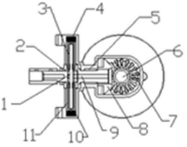
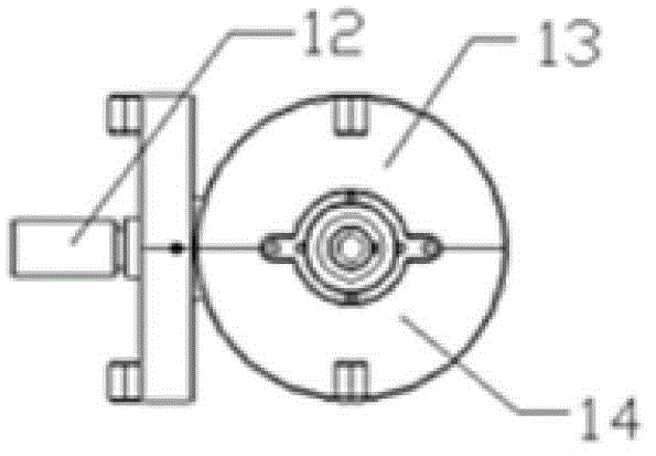
[0031] In the present invention, the clutch and the transmission functional mechanism are comprehensively designed into a power transmission assembly unit, and the magneto-rheological control technology is applied to the field of power transmission for the first time, which solves the problem of using magnetorheological fluid as the core medium of power transmission. The control method performs real-time control and management of the instantaneous, delayed clutch, and continuously variable speed functions required by the power load.
[0032] 1. Process procedure
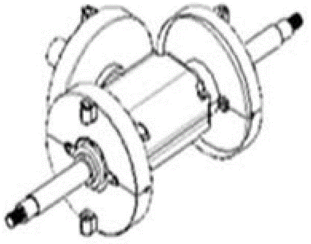
[0033] 1. First prepare the parts and magnetorheological fluid materials produced according to the attached drawings.
[0034] Concretely, comprise by coupling 12, clutch plate shaft 11, clutch frame shaft 9, clutch bearing 5, power gear, reversing gear 7, reversing shaft 6, reversing bearing form speed change commutator assembly; A magneto-rheological clutch assembly composed of a sheet shaft 1, a clutch housing br...
PUM
Abstract
The invention relates to the technical field of power clutch transmission devices, in particular to a magneto-rheological clutch transmission device. The magneto-rheological clutch transmission device comprises a clutch disc shaft, a clutch shell carrier, magneto-rheological fluid, a clutch coil, a clutch bearing, a reversing shaft, a reversing gear, a power gear, a clutch frame shaft, a coil frame, a clutch shell, a coupling, an upper shell body and a lower shell body in an assembling mode. When a vehicle is started, the coupling inputs power to the clutch disc shaft; when the vehicle is driven away, current is input into the clutch coil, magnetorheology is changed from liquid state into solid state, the power passes the power gear and the reversing gear through the clutch disc and is transmitted to the reversing shaft; and when the vehicle is stopped, the current of the clutch coil is cut off, the magnetorheology is changed from the solid state into liquid state, and the clutch disc shaft idles and loses driving power. The magneto-rheological clutch transmission device effectively resolves the technical problems of lightweight products, simple structures, reduced materials, intelligent control, and the like, can effectively lower production cost, and provides powerful support for popularization of novel materials, novel technology and novel process and technology upgrading of the products.
Description
[technical field] [0001] The invention relates to the technical field of power clutch transmission devices, in particular to a magneto-rheological clutch transmission device and methods and applications for clutch and speed change thereof, which are suitable for small and medium-sized electric vehicles, engineering logistics vehicles, agricultural vehicles, and lifting and transporting vehicles , Marine driving devices, mechanical power devices, etc. [Background technique] [0002] Magnetorheological fluid is a new type of phase change material. It is a magnetic particle suspension mixed with high magnetic permeability and low hysteresis (micron or even nanoscale) soft magnetic particles and non-magnetic liquid. When there is no magnetic field, the suspended particulate iron particles move freely with the liquid; when a magnetic field is applied, these suspended particulate iron particles are attracted to each other, forming a series of chain structures from one pole of the ...
Claims
Application Information
Patent Timeline
Application Date:The date an application was filed.
Publication Date:The date a patent or application was officially published.
First Publication Date:The earliest publication date of a patent with the same application number.
Issue Date:Publication date of the patent grant document.
PCT Entry Date:The Entry date of PCT National Phase.
Estimated Expiry Date:The statutory expiry date of a patent right according to the Patent Law, and it is the longest term of protection that the patent right can achieve without the termination of the patent right due to other reasons(Term extension factor has been taken into account ).
Invalid Date:Actual expiry date is based on effective date or publication date of legal transaction data of invalid patent.