
A tension balance suspension device

A suspension device and tension technology, applied in transportation and packaging, shock absorbers, elevators, etc., can solve problems such as control and stay, and achieve the effect of reducing cross-sectional area, small energy, and continuously adjustable damping force

Active Publication Date: 2021-07-30
NANTONG UNIVERSITY
View PDF5 Cites 0 Cited by
  • Summary
  • Abstract
  • Description
  • Claims
  • Application Information

AI Technical Summary

Problems solved by technology

[0003] At present, the vibration suppression of mine hoisting mostly stays in the aspect of parameter optimization, and there is no effective actuator to control the vibration that occurs during the hoisting process

Method used


Image

  • A tension balance suspension device
  • A tension balance suspension device
  • A tension balance suspension device

Examples


Embodiment 1

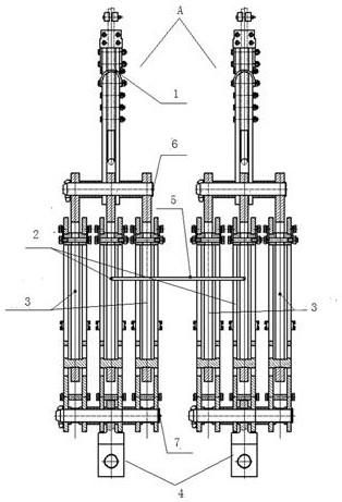
[0021] Embodiment 1: as figure 1 The shown tension balance suspension device includes two tension balance units A, the tension balance unit includes a rope ring 1, a balance oil cylinder 2, two magneto-rheological dampers 3 and a reversing fork 4; the balance oil cylinder includes the contents A cylinder block with hydraulic oil and a piston rod inserted into the cylinder block at one end; the two ends of the balance cylinder 2 are respectively connected to the rope ring 1 and the reversing fork 4, and the rope ring and the reversing fork 4 are located at On the central axis of the balance oil cylinder; the two ends of the magneto-rheological damper are respectively rigidly connected to the two ends of the balance oil cylinder, and the two magneto-rheological dampers are symmetrically arranged on both sides of the balance oil cylinder; The oil cylinders of each tension balance unit are connected with a connecting oil pipe 5, so that the hydraulic oil in each oil cylinder can f...

Embodiment 2

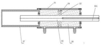
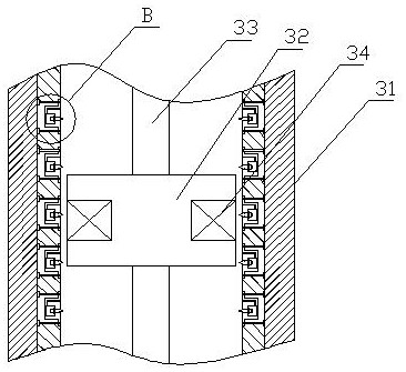
[0028] The inner side wall of the magneto-rheological cylinder 31 has a plurality of insertion slots 311, and the adjustment block 35 with the iron part is inserted into the insertion slots. Using the magnetic field generated by the excitation coil of the magnetorheological damper to attract the adjustment block, the cross-sectional area of ​​the gap between the piston body and the inner wall of the magnetorheological cylinder can be reduced, so that the excitation coil can greatly The damping force when the magnetorheological fluid passes through the gap is increased and the damping force adjustment range of the magnetorheological damper is increased.

[0029] The end of the regulating block opposite to the inside of the magnetorheological cylinder has a first inclined surface 351 and a second inclined surface 352, and the first inclined surface and the second inclined surface are respectively in the gap with the magnetorheological fluid. The two directions of reciprocating f...


PUM


Abstract

The invention relates to a tension balance suspension device, comprising at least two tension balance units, the tension balance unit includes a rope ring, a balance oil cylinder, at least one magneto-rheological damper and a reversing fork; the balance oil cylinder includes a hydraulic pressure The oil cylinder body and the piston rod with one end plugged into the oil cylinder body; the two ends of the balance oil cylinder are respectively connected to the rope ring and the reversing fork, and the rope ring and the reversing fork are located in the center of the balance oil cylinder. On the axis; the two ends of the magneto-rheological damper are rigidly connected to the two ends of the balance oil cylinder respectively; the oil cylinder bodies of each tension balance unit are connected with a connecting oil pipe, so that the hydraulic oil in each oil cylinder body can pass through The connecting oil pipe flows between the oil cylinder blocks of each tension balance unit. The device can not only balance the tension between the wire ropes, but also effectively suppress the vibration of the wire ropes, ensuring the stability of the hoisting system.

Description

technical field [0001] The invention relates to a tension balance device, in particular to a tension balance suspension device based on a magneto-rheological damper. Background technique [0002] Due to the characteristics of ultra-deep, high-speed, heavy load, strong time-varying and large inertia, the deep mine hoisting system is prone to violent fluctuations and sudden changes in dynamic load due to vibration under multiple disturbance excitations, which will cause huge impacts on the hoisting container and seriously threaten hoisting. Safety. Therefore, it is necessary to suppress the vibration of the wire rope to ensure the smooth operation of the lifting container. [0003] At present, the vibration suppression of mine hoisting mostly stays in the aspect of parameter optimization, and there is no effective actuator to control the vibration that occurs during the hoisting process. Especially in the hoisting of ultra-deep wells, due to many factors such as large end lo...

Claims


Application Information

Patent Timeline
Patent Type & Authority Patents(China)
IPC IPC(8): B66B7/10F16F9/53
CPCB66B7/10F16F9/535
Inventor 姚建南朱昱朱维南张福豹张旭东刘建鹏
Owner NANTONG UNIVERSITY
Learn More