Supercharge Your Innovation With Domain-Expert AI Agents!

Light source device and projector

A technology of light source device and projector, which is applied in the direction of lighting device, projection device, cooling/heating device of lighting device, etc., and can solve problems such as complicated structure

Active Publication Date: 2013-06-19
SANYO ELECTRIC CO LTD
View PDF3 Cites 0 Cited by
  • Summary
  • Abstract
  • Description
  • Claims
  • Application Information

AI Technical Summary

Problems solved by technology

[0005] However, in the structure disclosed in the aforementioned Patent Document 1, since the inflow path and the outflow path need to be provided substantially parallel to the light emitting element, there is a problem that the structure is complicated.

Method used


Image

  • Light source device and projector
  • Light source device and projector
  • Light source device and projector

Examples


Embodiment Construction

[0025] Hereinafter, embodiments of the present invention will be described based on the drawings. In addition, in the following drawings, the same reference symbol is attached|subjected to the same or equivalent part, and the description is not repeated.

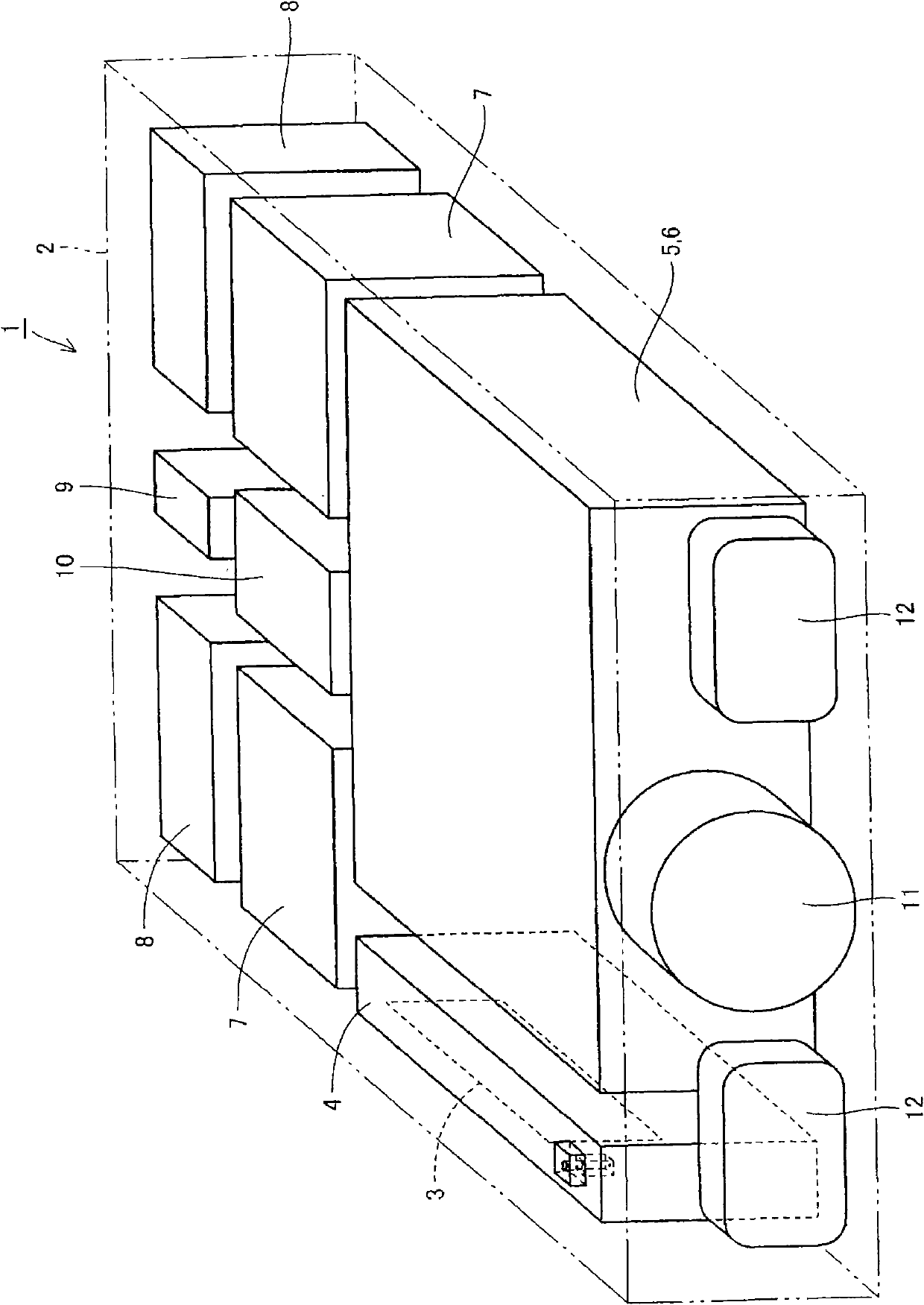
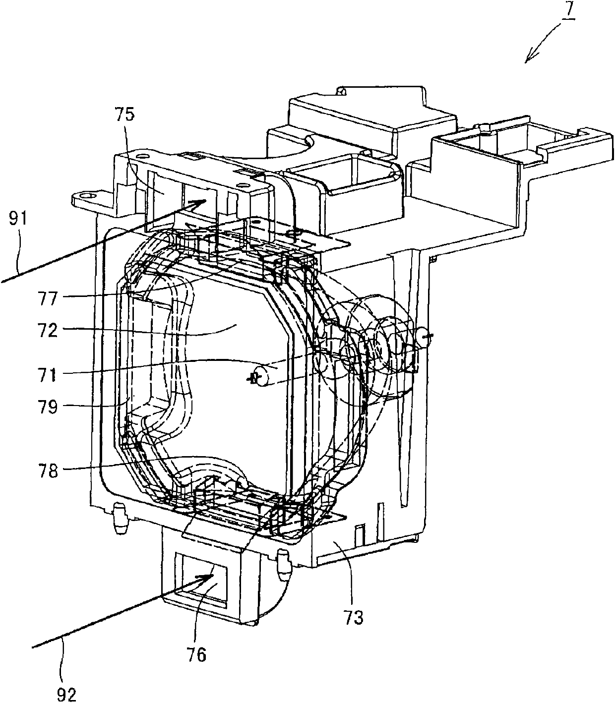
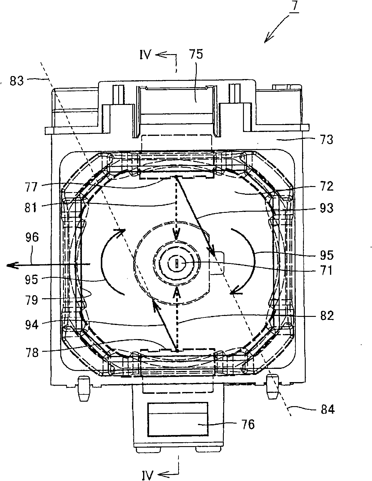
[0026] figure 1 It is a schematic diagram showing the configuration of a projector according to an embodiment of the present invention. in addition, figure 2 is showing figure 1 A schematic perspective view of the structure of the lamp unit included in the projector. in addition image 3 It is a schematic plan view which shows the state which looked at the lamp unit from the front. in addition, Figure 4 yes image 3 A schematic cross-sectional view along line IV-IV.

[0027] refer to figure 1 , in the housing 2 of the projector 1 of this embodiment, there are provided: a projection lens 11 for projecting an image; a pair of speakers 12 that are arranged to sandwich the projection lens 11 and output sound; The opt...


PUM


Abstract

A lamp unit configuring a light source device capable of efficiently cooling a light source by a simple structure includes a light source and a plurality of air outlets for discharging the cooling air for cooling the light source. The plurality of air outlets include a first air outlet for discharging the cooling air in a first direction and a second air outlet for discharging the cooling air in a second direction. The cooling air discharged through the first air outlet is different in airflow rate from the cooling air discharged through the second air outlet, and the first direction is different from the second direction when viewed in the direction of the optical axis of the light source.

Description

technical field [0001] The present invention relates to a light source device and a projector, and is further particularly specified as an efficiently cooled light source device and a projector equipped with the light source device. Background technique [0002] In recent years, along with the high performance of devices such as projectors including light source devices as structural components, higher luminance has been demanded for light source devices. Furthermore, in order to respond to the demand for higher luminance, there is a tendency to use a light source with a large amount of light as a light source device. Such a light source with a large amount of light often generates a large amount of heat, and effective cooling is required. [0003] In contrast, for example, a light source device has been proposed in which an inflow path and an outflow path of a cooling fluid are arranged substantially parallel to a surface of a light-emitting element base on which a light-e...

Claims


Application Information

Patent Timeline
Patent Type & Authority Patents(China)
IPC IPC(8): F21V29/02G03B21/16
CPCG03B21/20G03B21/16
Inventor 神原稔昌吉村太一广内康之
Owner SANYO ELECTRIC CO LTD
Features
  • R&D
  • Intellectual Property
  • Life Sciences
  • Materials
  • Tech Scout
  • Unparalleled Data Quality
  • Higher Quality Content
  • 60% Fewer Hallucinations
Learn More