Rotating angle sensor

A technology of rotation angle and sensor, which is applied in the direction of instruments, mechanical devices to transmit sensing components, measuring devices, etc., which can solve the problems of rotation angle sensor measurement deviation, failure, and low detection accuracy

Active Publication Date: 2010-06-23
TOKYO COSMOS ELECTRIC CO LTD
View PDF6 Cites 24 Cited by
  • Summary
  • Abstract
  • Description
  • Claims
  • Application Information

AI Technical Summary

Problems solved by technology

[0005] In this conventional example, the bearing 2 is interposed between the flange 3A integrally formed on the rotor 3 and the bracket 4. Therefore, the axial movement of the rotor 3 and the inclination of the shaft relative to the casing are restricted, but since the rotor 3 is able to rotate relative to the bearing 2, so both of them are somewhat malfunctioning (ガタ)
As a result, the magnet 5 comes into contact with the magnetic sensor 8 and is damaged...

Method used


Image

  • Rotating angle sensor
  • Rotating angle sensor
  • Rotating angle sensor

Examples


Embodiment Construction

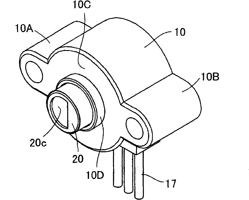
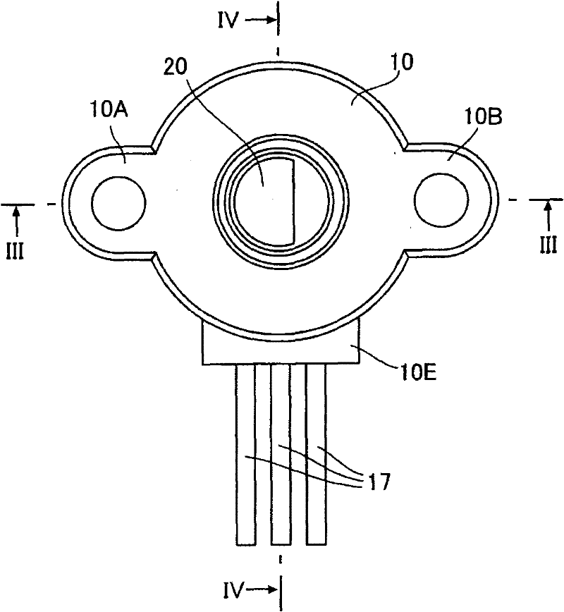
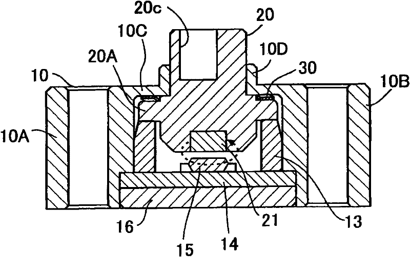
[0017] figure 1 Represent the perspective view of the first embodiment of the rotation angle sensor of the present invention, figure 2 represents its floor plan, image 3 and Figure 4 Respectively figure 2 III-III section and IV-IV section of the rotation angle sensor in Fig. The rotation angle sensor has: a case 10 formed of a substantially cylindrical insulator having mounting protrusions 10A, 10B on both sides; ; The wave washer (wave seat gold) 30 installed between the flange 20A formed at the axially middle part of the rotor 20 and the front wall of the housing 10; the magnet 21 fixed to the other end of the rotor 20 located in the housing 20; The ring bearing 13 that supports the inner end of the rotor 20 through one end in the casing 10; the wiring board 14 that supports the other end of the ring bearing 13; A magnetic sensor IC 15 (integrated circuit) mounted on the wiring board 14 facing at a distance from each other;

[0018] In addition, in Figure 8 In th...


PUM


Abstract

The invention relates to a rotating angle sensor. A rotor (20) with a flange (20A) can be rotatably configured in a housing (10), the front end of the rotor is projected from an opening formed on the front wall (10C) of the housing. In the housing (10), the front of an annular bearing (13) supports the rear end of the flange (20A) by a resilient waveform washer (30), and the rear end of the annular bearing is fixed on a distribution substrate (14). A magnet (21) is fixed at the rear end of the rotor, and a magnetic sensor IC (15) is mounted on the distribution substrate (14) at an interval from the magnet and opposite to the magnet.

Description

technical field [0001] The present invention relates to a rotation angle sensor for detecting the rotation angle of a rotation shaft used in motor vehicles, industrial machines, and the like. Background technique [0002] As a prior art, there is known a rotation angle sensor in which a magnet is provided at the tip of a rotating rotor connected to a rotating shaft, and a magnetic sensor such as a magneto-resistive element facing the magnet at a distance is used to detect the rotation angle sensor. the rotation angle. As the prior art mentioned above, Figure 8 , for example, represents a cross section of the rotation angle sensor disclosed in Patent Document 1. FIG. [0003] exist Figure 8 In the conventional example, the bearing 2 is inserted and fixed in a hole formed in the front wall of the box-shaped casing 9, and the rotor 3 passes through the shaft hole of the bearing 2. A disc-shaped bracket 4 is fixed to the lower end of the rotor 3 inside the housing 9 , and a ...

Claims


Application Information

Patent Timeline
IPC IPC(8): G01D5/04G01B7/30
Inventor 田中宏之佐藤浩介市仓学
Owner TOKYO COSMOS ELECTRIC CO LTD
Why Eureka
Try Eureka