
Method and device for measuring environment temperature change and magnetic induction strength

A technology of magnetic induction intensity and ambient temperature, applied in the direction of measuring devices, the size/direction of the magnetic field, and the use of magneto-optical equipment for magnetic field measurement, etc., can solve problems such as complex execution

Inactive Publication Date: 2010-06-23
UNIV OF ELECTRONICS SCI & TECH OF CHINA
View PDF5 Cites 8 Cited by
  • Summary
  • Abstract
  • Description
  • Claims
  • Application Information

AI Technical Summary

Problems solved by technology

They are extrinsic sensing methods and are complex to implement

Method used


Image

  • Method and device for measuring environment temperature change and magnetic induction strength
  • Method and device for measuring environment temperature change and magnetic induction strength
  • Method and device for measuring environment temperature change and magnetic induction strength

Examples


specific Embodiment approach 1

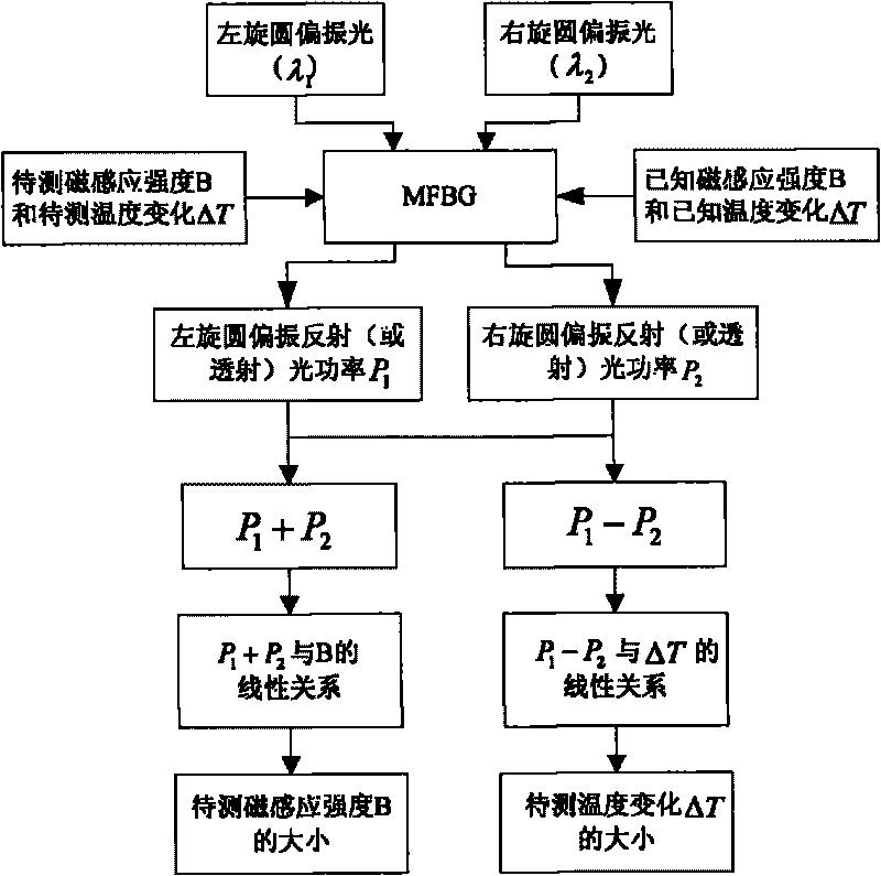
[0041] A measuring device for ambient temperature change and magnetic induction, such as Figure 4 , 5 As shown, it includes a polarized light emitting unit, a magneto-optical fiber Bragg grating (MFBG), a polarized light detecting unit and a data processing unit.

[0042] The polarized light emitting unit includes the first and second narrowband light sources, the first and second optical fiber polarizers, the first and second optical polarization controllers and optical wavelength division multiplexer WDM; the wavelength emitted by the first narrowband light source is λ 1 After being polarized by the first optical fiber polarizer, the light passes through the first optical polarization controller to generate left-handed circularly polarized light; the wavelength emitted by the second narrow-band light source is λ 2 After being polarized by the second optical fiber polarizer, the light passes through the second optical polarization controller to generate right-handed circula...

specific Embodiment approach 2

[0046] A measuring device for ambient temperature change and magnetic induction, such as Figure 4 , 6 As shown, it includes a polarized light emitting unit, a magneto-optical fiber Bragg grating (MFBG), a polarized light detecting unit and a data processing unit.

[0047] The polarized light emitting unit includes the first and second narrowband light sources, the first and second optical fiber polarizers, the first and second optical polarization controllers and optical wavelength division multiplexer WDM; the wavelength emitted by the first narrowband light source is λ 1 After being polarized by the first optical fiber polarizer, the light passes through the first optical polarization controller to generate left-handed circularly polarized light; the wavelength emitted by the second narrow-band light source is λ 2 After being polarized by the second optical fiber polarizer, the light passes through the second optical polarization controller to generate right-handed circula...


PUM


Abstract

The invention discloses a method and a device for measuring environment temperature change and magnetic induction strength, belongs to the field of photoelectric technology, relates to optical fiber sensing technology, in particular to a method and a device for measuring magnetic induction strength ( or optical fiber Verdet constant) and temperature change based on magneto-optical fiber Bragg optical grating (MFBG). The invention adopts magneto-optical fiber Bragg optical grating, respectively utilizes levorotation and dextrorotation circularly polarized light to emit into MFBG according to intrinsic sensing mode and reflectivity and transmission property, and realizes measuring magnetic induction strength ( or optical fiber Verdet constant) and temperature change simultaneously by detecting luminous power reflection (or transmission) circularly polarized light of MFBG, thus realizing multiple parameter incoherent detection, and having the advantages of convenience, easiness and omission of temperature compensation.

Description

technical field [0001] The invention belongs to the field of optoelectronic technology and relates to optical fiber sensing technology, in particular to a method and device for measuring magnetic induction (or optical fiber Verdet constant) and temperature changes based on a magneto-optic optical fiber Bragg grating (MFBG). Background technique [0002] Optical fiber sensing technology is a new type of sensing technology developed rapidly along with the development of optical fiber and optical fiber communication technology. It takes the optical signal as the carrier of the information to be measured, uses the optical fiber as the transmission medium and the sensing medium, and extracts the measured information in the form of an optical signal. Specifically, the optical fiber sensor directly or indirectly detects the characteristic parameters of the light wave in the optical fiber (such as light intensity, wavelength, phase, amplitude, etc.) A device that detects various ph...

Claims


Application Information

Patent Timeline
Patent Type & Authority Applications(China)
IPC IPC(8): G01R33/032G01K11/32G01K11/3206
Inventor 武保剑吴士娟邱昆
Owner UNIV OF ELECTRONICS SCI & TECH OF CHINA
Learn More