

Zoom infrared optical system, zooming device and manufacturing method thereof
An infrared optical system and variable focal length technology, applied in optics, optical components, installation, etc., can solve the problems of limited field of view and the number of moving components, long axial length of zoom lens group, and limited freedom of optical design. , to achieve the effect of increasing the telephoto transmittance, reducing the number of system lenses, and improving the detection ability
- Summary
- Abstract
- Description
- Claims
- Application Information
AI Technical Summary
Problems solved by technology
Method used
Image

Examples
Embodiment Construction
[0045] The present invention is further described as follows in conjunction with accompanying drawing and embodiment:
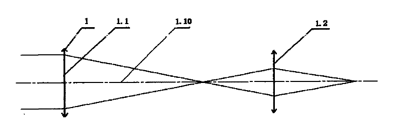
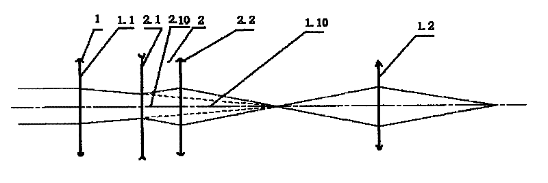
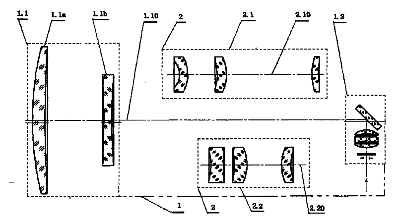
[0046] Such as figure 1 , 2 , Shown in 3, is an embodiment of a kind of zoom infrared optical system of the present invention:
[0047] A zoom infrared optical system, it has a telephoto lens group 1 and zoom lens group 2, the lens materials are optical materials that can work in the infrared band; the telephoto lens group 1 is composed of front fixed lens group 1.1 and The rear fixed lens group 1.2 constitutes; the variable power lens group 2 is located between the front fixed lens group 1.1 and the rear fixed lens group 1.2: when telephoto imaging, the variable power lens group 2 is located between the front fixed lens group 1.1 and the rear fixed lens group 1.2 Outside the optical path between; when zooming imaging, the variable power lens group 2 cuts in the optical path between the front fixed lens group 1.1 and the rear fixed lens group 1.2 through th...
PUM
 Abstract
Description
Claims
Application Information