Signal transmission module

A technology of signal transmission module and signal line, which is applied in the direction of transmission system, waveguide devices, electrical components, etc., can solve the problems of narrow application frequency band and insufficient ability to suppress harmonics, and achieve strong harmonic suppression ability and application frequency band wide effect

Inactive Publication Date: 2010-06-23
HUAWEI TECH CO LTD
View PDF0 Cites 4 Cited by
  • Summary
  • Abstract
  • Description
  • Claims
  • Application Information

AI Technical Summary

Problems solved by technology

[0004] In the process of realizing the present invention, the inventor found that the existing technology has the disadvantages that the ability to suppress harmonics is not strong enough, and the application frequency band is narrow

Method used


Image

  • Signal transmission module
  • Signal transmission module
  • Signal transmission module

Examples


Embodiment Construction

[0022] In order to make the object, technical solution and advantages of the present invention clearer, the present invention will be further described in detail below through specific embodiments and related drawings.

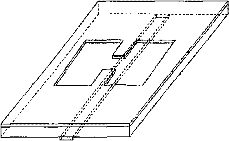
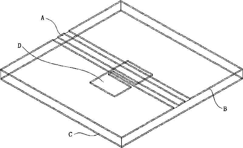
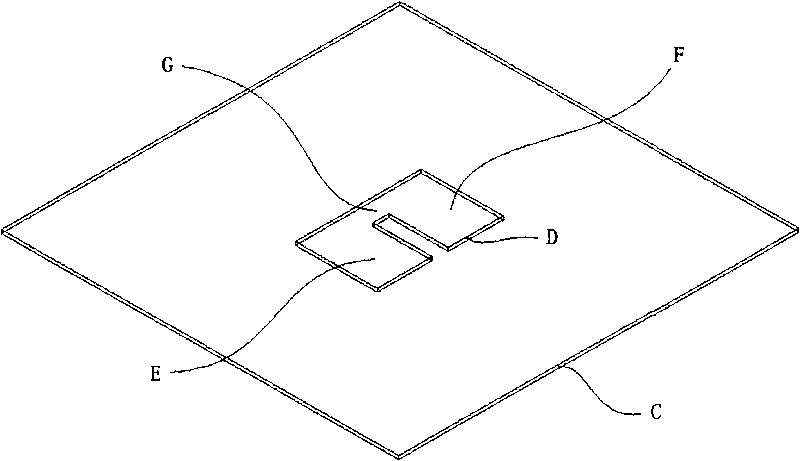
[0023] see figure 2 and image 3 , an embodiment of a signal transmission module of the present invention, including a circuit board; the circuit board includes a first conductor layer and a second conductor layer located on both surfaces of the circuit board; the first conductor layer includes signal lines A and The side ground B, the side ground B is located on both sides of the signal line A; the second conductor layer is provided with a bottom ground C, and a defect zone is opened on the bottom surface C, and the defect zone is in the The projection on the first conductor layer overlaps with the signal line A, and the side ground B is electrically connected to the bottom ground C.

[0024] In the embodiment of the present invention, side grounds B are p...


PUM


Abstract

The invention discloses a signal transmission module, which comprises a circuit board, wherein the circuit board comprises a first conductor layer and a second conductor layer, which are respectively arranged on two surfaces of the circuit board; the first conductor layer comprises a signal wire and lateral ground, and the lateral ground is arranged at two sides of the signal wire; and the second conductor layer is arranged on the bottom surface ground, the bottom surface ground is provided with an imperfect tape, the projection of the imperfect tape on the first conductor layer is overlapped with the signal wire, and the lateral ground is electrically connected with the bottom surface ground. The signal transmission module has the advantages of strong harmonics inhibition capacity and wide application frequency band.

Description

technical field [0001] The invention relates to the technical field of communication, in particular to a signal transmission module. Background technique [0002] In 1999, Korean scholar J.I.Park and others proposed DGS (Defected Ground Structure) on the basis of studying the PBG (Photonic Band Gap) structure, that is, etched on the bottom surface of the circuit board with a certain shape. The defect zone will disturb the distribution of the shielding current on the bottom surface, thereby changing the electrical characteristics of the signal line on the surface of the circuit board. DGS has the same bandgap and slow-wave characteristics as the PBG structure, but its form is simpler than that of PBG, and it is suitable for a wide frequency band. It has been widely used in the field of radio frequency communication. [0003] The existing technology design DGS mainly adopts the form of standard microstrip line, see figure 1 , DGS designed with standard microstrip line includ...

Claims


Application Information

Patent Timeline
Patent Type & Authority Applications(China)
IPC IPC(8): H01P1/212H01P3/08H04B1/00
Inventor 彭旭
Owner HUAWEI TECH CO LTD
Why Eureka
Try Eureka