Fiber link fault recognition method, device and system

A fiber optic link and fault identification technology, which is applied in the field of optical communication, can solve problems such as failure to identify fault types, failure to identify fault types in real time, etc., and achieve the effects of improving maintenance efficiency, improving user experience, and reducing personnel costs

Inactive Publication Date: 2010-06-23
甄雅丽
View PDF3 Cites 51 Cited by
  • Summary
  • Abstract
  • Description
  • Claims
  • Application Information

AI Technical Summary

Problems solved by technology

[0010] Embodiments of the present invention provide a fiber link fault identification method, device and system to overcome the defects of the prior art that cannot identify the type of fault and cannot identify the type of fault in real time

Method used


Image

  • Fiber link fault recognition method, device and system
  • Fiber link fault recognition method, device and system
  • Fiber link fault recognition method, device and system

Examples


Embodiment Construction

[0046] The technical solutions of the present invention will be described in further detail below with reference to the accompanying drawings and embodiments.

[0047] The inventor has found through a large number of experiments that all faults will last for a period of time, and the corresponding parameters of the optical signal will have a dynamic change process when a fault occurs. However, each kind of fault has different changes of optical signal parameters.

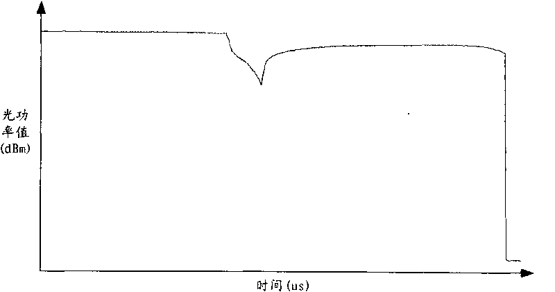
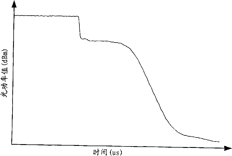
[0048] Figure 2a It is the optical power variation curve during the fiber break process in the passive optical network according to the embodiment of the present invention. Figure 2b It is the optical power change curve during the process of the optical fiber connector in the passive optical network of the embodiment of the present invention falling off. Such as Figure 2a and Figure 2b As shown, the optical power change curves are different when the optical fiber is broken and the SC / PC optical fiber connect...


PUM


Abstract

The invention relates to a fiber link fault recognition method, a device and a system. The method comprises the following steps: detecting power of one or a plurality of optical network units in real time; when detecting a fault in the fiber link corresponding to a certain optical network unit, extracting at least two upstream optical power values in the fiber link fault occurrence process; and according to the upstream optical power values in the fiber link fault occurrence process, recognizing the fault type of the fiber link corresponding to the optical network unit. The fiber link fault recognition method of the embodiment of the invention detects whether a fault exists in the fiber link corresponding to the optical network unit in real time by detecting the power of the optical network units in real time. When detecting a fault in the fiber link corresponding to the optical network unit, the upstream optical power values in the fiber link fault occurrence process are extracted, and the fault type of the fiber link is recognized in real time according to extracted power values.

Description

technical field [0001] The invention belongs to the field of optical communication, in particular to an optical fiber link fault identification method, device and system. Background technique [0002] With the advent of the information age, people's demand for bandwidth is increasing. As the last mile access network, Passive Optical Network (PON) technology has become the " The best technology for the network transformation of light into copper. At present, the mainstream technologies of passive optical network are Ethernet Passive Optical Network (EPON for short) and Gigabit-Capable Passive Optical Network (GPON for short). There are already tens of millions of passive optical networks in Asia. Ethernet passive optical network users, operators in North America and Europe have begun the deployment of gigabit passive optical networks. In the next few years, passive optical networks will play a leading role in the broadband access market and will usher in large-scale commerc...

Claims


Application Information

Patent Timeline
Patent Type & Authority Applications(China)
IPC IPC(8): H04B10/08H04Q11/00H04B10/075
Inventor 彭桂开杨素林欧阳伟龙何孝月
Owner 甄雅丽
Why Eureka
Try Eureka