
Multi-interface fusion method of communication node

A technology of communication node and fusion method, applied in the field of communication, can solve the problems of lack of knowledge and ability, inflexible configuration, inconvenient user of communication node interface management and maintenance method, etc., to achieve the effect of convenient interface management and maintenance

Inactive Publication Date: 2010-06-23
UNIV OF ELECTRONICS SCI & TECH OF CHINA
View PDF0 Cites 26 Cited by
  • Summary
  • Abstract
  • Description
  • Claims
  • Application Information

AI Technical Summary

Problems solved by technology

But in fact, it is possible that the campus network connected to the Ethernet cannot provide Internet access capabilities, so in order to access Internet resources, users usually have to disconnect the Ethernet or force IE not to use the Ethernet.
However, if the user wants to access the campus network information resources through IE, and these resources can only be accessed through the Ethernet connection, the user must reset the settings
And when users want to access campus network and Internet resources at the same time, users have to build local routing tables by themselves, but most of the users do not have the relevant knowledge and ability, and this configuration is not flexible, because when the user's communication When the computer terminal of the node is connected to another Ethernet environment with Internet access, the computer must be reconfigured, so the interface management and maintenance methods of the existing communication nodes have caused great inconvenience to users

Method used


Image

  • Multi-interface fusion method of communication node
  • Multi-interface fusion method of communication node
  • Multi-interface fusion method of communication node

Examples


Embodiment Construction

[0020] In order to better understand the present invention, the present invention will be described in more detail below in conjunction with the accompanying drawings and specific embodiments. In the following description, when detailed descriptions of existing prior art may obscure the subject matter of the present invention, such descriptions will be omitted here.

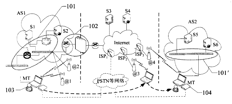
[0021] figure 1 It is a schematic diagram of a typical application scenario of the multi-interface fusion method of the communication node of the present invention

[0022] A communication node is usually connected to a local area network environment, which is called an autonomous area (AS).

[0023] Such as figure 1 As shown, the communication node MT can access the autonomous domain AS1 through a wired network such as Ethernet or a wireless network @1 and / or @2, wherein all IP addresses on the autonomous domain AS1 do not appear on the public network, but the hosts on this domain are all External network res...


PUM


Abstract

The invention discloses a multi-interface fusion method of a communication node, which comprises the following steps: establishing an address table and an interface table; regularly testing the state and the parameter information of each network interface by a state / parameter maintenance module; wiring the state and parameter information of each network interface into the interface table and updating the interface table; automatically distributing business data to be sent out by the communication node by a business leading module according to the interface state information of the interface table; and sending out the business data through the set network interface so that the defects of inconvenient interface management and maintenance of the manual closing of a network interface by users or manual route table configuration in the prior art. At the same time, when a plurality of network interfaces capable of visiting the outer network or the inner network exist, the optimal network interface is further selected for outwards sending according to the performance parameter of the outer network connection of the interface table, or the business data carry out load balance on the network interfaces, so the business data can be distributed to the optimal network interface, or the business data can be transmitted and distributed to a plurality of network interfaces, and the integral transmission bandwidth of the outer network or the inner network of the system is indirectly improved.

Description

technical field [0001] The invention relates to the technical field of communication, in particular to a method for merging interfaces in a communication node with multiple network interfaces. Background technique [0002] With the rapid development of microelectronics technology and electronic communication technology, as well as the wide application of Internet technology and business, mobile computing and personal communication have become the mainstream. With the emergence of various wired and wireless communication technology standards and interfaces, the boundaries between computer terminals and communication terminals are becoming increasingly blurred, and they have become an access communication node in the communication network. [0003] Communication node access includes wired methods such as ordinary telephones, modems, and Ethernet, as well as wireless personal area networks represented by Bluetooth, wireless local area networks represented by WiFi (IEEE802.11 se...

Claims


Application Information

Patent Timeline
IPC IPC(8): H04L29/12H04L12/24H04L29/06H04L12/56
Inventor 邝育军隆克平刘健徐杰
Owner UNIV OF ELECTRONICS SCI & TECH OF CHINA
Learn More