Centralized electricity-saving lamp power source

An energy-saving lamp, centralized technology, applied in the direction of electric light source, light source, electrical components, etc., can solve the problem of high failure rate of integrated electronic energy-saving lamps, and achieve the effect of small occupied space, improved power factor and low cost

Inactive Publication Date: 2010-06-23
SHANGHAI DIANJI UNIV
View PDF0 Cites 11 Cited by
  • Summary
  • Abstract
  • Description
  • Claims
  • Application Information

AI Technical Summary

Problems solved by technology

For a long time, people's attention has been focused on high-power compensation systems based on enterprises, and few people have considered the development and design of small power factor ...

Method used


Image

  • Centralized electricity-saving lamp power source
  • Centralized electricity-saving lamp power source
  • Centralized electricity-saving lamp power source

Examples


Embodiment Construction

[0014] The present invention will be further described below in conjunction with the embodiments and with reference to the accompanying drawings.

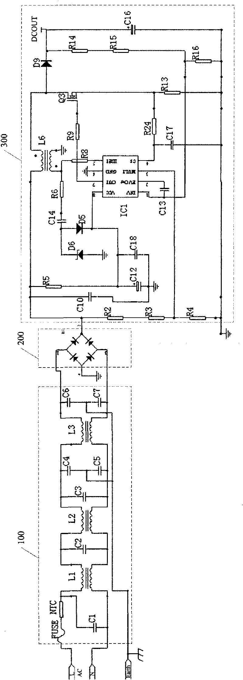
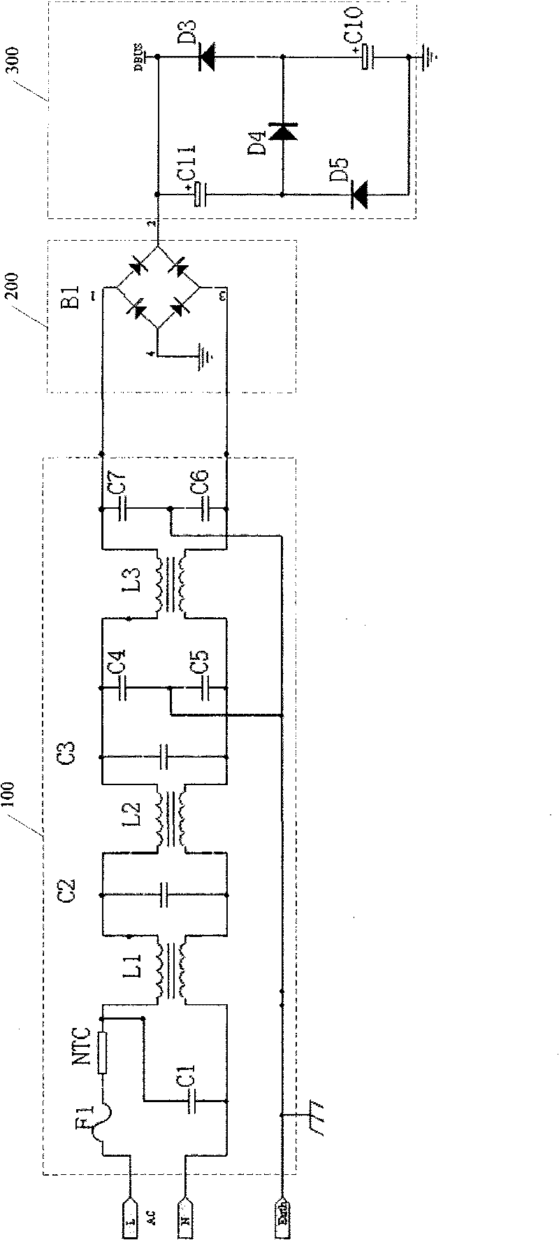
[0015] see figure 2 , figure 2 It is a schematic circuit diagram of a specific embodiment of a centralized energy-saving lamp power supply of the present invention. The centralized energy-saving lamp power supply includes an EMC filter circuit 100 , a bridge rectifier circuit 200 and a PFC circuit 300 sequentially connected.

[0016] Wherein, the PFC circuit 300 includes an embedded PFC chip and its peripheral parameter circuit, a BOOST boost inductor L6, a MOS transistor Q3, and an electrolytic capacitor C16. As an optional technical solution, the PFC circuit 300 is an active PFC circuit, that is, an active power factor correction PFC circuit.

[0017] Active power factor correction PFC circuits mainly include basic circuit forms such as boost type, buck type, boost-buck type and flyback type, among which the boost type active...


PUM


Abstract

The invention discloses a centralized electricity-saving lamp power source, comprising an EMC filter circuit, a bridge rectifier circuit and a PFC circuit which are sequentially connected, the PFC circuit comprises an embedded-type PFC chip and external parameter circuit, a BOOST boost inductor, an MOS pipe, and a main electrolytic capacitor, wherein, the PFC circuit is the active or passive PFC circuit. The centralized electricity-saving lamp power source provided by the invention has low cost, small occupied space, long service life, and decreased conducted interference of the whole lighting system.

Description

【Technical field】 [0001] The invention relates to a power supply device, in particular to a centralized energy-saving lamp power supply. 【Background technique】 [0002] The integrated electronic energy-saving lamp is a new type of energy-saving light source that has been popular in domestic and foreign markets recently, such as figure 1 Shown is the circuit principle diagram of the integrated electronic energy-saving lamp in the prior art. It has notable features such as small size, light weight, high luminous efficiency, and low-voltage quick start. It can directly replace incandescent bulbs and is used in various lighting and decoration places. As a key energy-saving product, it is widely used in factories, public buildings, and households. get a lot of use. However, the existing integrated electronic energy-saving lamps have the following problems in application: [0003] First of all, the power factor of integrated electronic energy-saving lamps is low. In an AC circ...

Claims


Application Information

Patent Timeline
IPC IPC(8): H05B41/295
Inventor 曾宪文曾祥绪
Owner SHANGHAI DIANJI UNIV
Why Eureka
Try Eureka