Machine arrangement for machining bar-like workpieces having a device for workpiece support

A technology of mechanical structure and processing rod, which is applied to metal processing mechanical parts, supports, positioning devices, etc., can solve the problem of the immovability of the workpiece seat, and achieve the effect of reliable functional support

Active Publication Date: 2010-06-23
TRUMPF WERKZEUGMASCHINEN GMBH & CO KG
View PDF1 Cites 20 Cited by
  • Summary
  • Abstract
  • Description
  • Claims
  • Application Information

AI Technical Summary

Problems solved by technology

The workpiece seating formed by the individual rollers of the prior art roller conveyor is not movable in the vertical direction

Method used


Image

  • Machine arrangement for machining bar-like workpieces having a device for workpiece support
  • Machine arrangement for machining bar-like workpieces having a device for workpiece support
  • Machine arrangement for machining bar-like workpieces having a device for workpiece support

Examples


Embodiment Construction

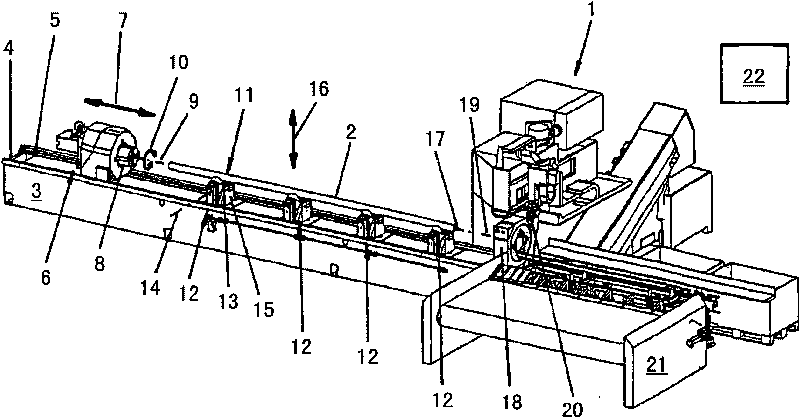
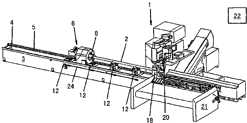
[0027] Such as figure 1 As shown, a machine structure 1 for processing a pipe 2 by cutting comprises a machine bed 3 comprising guide rails 4 for a rotating / feeding station (rotating / feeding table) 6 as workpiece moving means, 5. The rotation / feed station 6 is moved motor-driven on the guide rails 4 , 5 in the direction of the double-headed arrow 7 . On the side facing the tube 2 , the rotation / feed station 6 has a self-centering clamping chunk 8 . The clamping axis 9 of the clamping block 8 , which runs through the clamping center of the clamping block 8 , is indicated by a dotted line. The clamping block 8 can be rotated in a controlled manner about the clamping axis 9 in the direction of the double-headed arrow 10 . figure 1 The clamping block 8 is shown in the open state.

[0028]The tube 2 to be processed is supported against the force of gravity from below by a device 11 for supporting the workpiece, which device 11 is integrally formed in the machine bed 3 . In the...


PUM


Abstract

The invention relates to a machine arrangement (1) for machining bar-like workpieces, particularly pipes, comprising a machining device (20) for workpiece machining, a workpiece moving device (6) for moving workpieces (2) relative to the machining device (20), and a device (11) for workpiece support in the direction of gravity. The device (11) for workpiece support comprises at least one supporting roller (13) forming a workpiece contact surface on the outer circumference thereof. The workpiece contact surface on the outer circumference of the supporting roller (13) runs about a roller rotary axis (14) of the supporting roller (13) at a varying axis distance. The supporting roller (13) is controllably rotatably about the roller rotary axis (14) and thus is adjustable to various rotary settings.

Description

technical field [0001] The invention relates to a machine structure for machining rod-shaped workpieces, especially tubes, comprising [0002] Processing devices for processing workpieces; [0003] a workpiece moving device, by means of which the workpiece to be processed and / or the processed workpiece is adapted to be moved relative to the processing device; and [0004] means for supporting a workpiece, by means of which the workpiece can be supported against the effect of gravity in the transverse direction of said workpiece and at the same time moving towards the processing device and / or relative to the workpiece the vertical direction to take the vertical desired position to be supported, [0005] Wherein, the device for supporting the workpiece comprises at least one support roller, wherein the horizontal roller rotation axis of the support roller is oriented transversely of the workpiece and the support roller has a workpiece seat on its outer circumference extending ...

Claims


Application Information

Patent Timeline
Patent Type & Authority Applications(China)
IPC IPC(8): B23B13/02B23Q1/76B23Q7/05
CPCB23Q3/106B23Q1/76B23Q1/763B23B13/02B23Q2240/007Y10T29/5109
Inventor W·迪尔格I·卡拉施
Owner TRUMPF WERKZEUGMASCHINEN GMBH & CO KG
Why Eureka
Try Eureka