Wiring pattern checking device

A wiring pattern and inspection device technology, which can be used in measurement devices, material analysis by optical means, instruments, etc., and can solve problems such as longer inspection time.

Inactive Publication Date: 2010-06-30
USHIO DENKI KK
View PDF2 Cites 15 Cited by
  • Summary
  • Abstract
  • Description
  • Claims
  • Application Information

AI Technical Summary

Problems solved by technology

[0016] However, in this method, the measurement by reflected illumination light and the measurement by transmitted illumination light are performed twice for one inspection pattern, which increases the inspection time.

Method used


Image

  • Wiring pattern checking device
  • Wiring pattern checking device
  • Wiring pattern checking device

Examples


Embodiment Construction

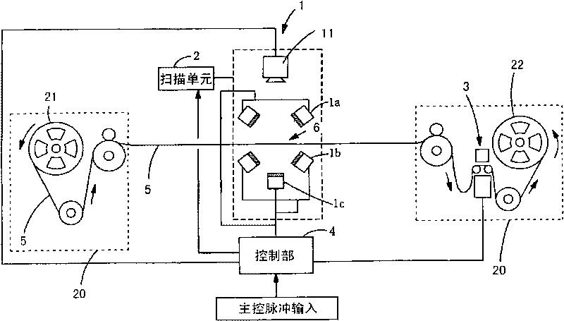
[0035] figure 1 is a block diagram of a wiring pattern inspection device according to an embodiment of the present invention. In addition, the following embodiments are described for the case where the substrate is a so-called TAB tape or COF (Chip On Film) film-shaped workpiece, but the present invention is also applicable to pattern inspection of other substrates with light transmission. .

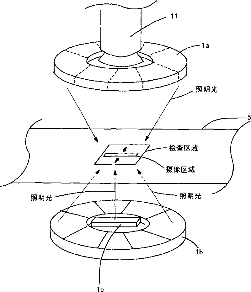
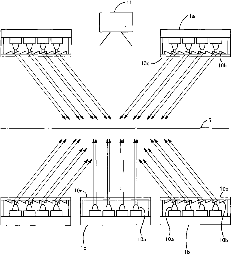
[0036] As shown in the figure, the pattern inspection device of this embodiment includes: a tape transport mechanism 20 composed of a delivery reel 21 or a take-up reel 22 for conveying the TAB tape 5 , and the TAB tape sent out from the delivery reel 21 5 The inspection unit 1 that irradiates the illumination light and photographs the inspection pattern 6, the scanning unit 2 that scans the inspection unit 1 on the inspection pattern 6 of the TAB tape, and the marking unit 3 that marks the defective pattern.

[0037] The marking part 3 is used to mark the pattern judged as defective ...


PUM

PropertyMeasurementUnit
widthaaaaaaaaaa
widthaaaaaaaaaa
widthaaaaaaaaaa

Abstract

In the pattern checking device, upper shape detection and lower shape detection for the pattern can be performed simultaneously. With respect to the TAB tape (5), a first illumination unit (1a) for obliquely radiating the illumination light from one side having a wiring pattern formed, a second illumination unit (1b) for obliquely radiating the illumination light from the side opposite to the side having the wiring pattern formed, and a third illumination unit (1c) for radiating the illumination light perpendicular to the checking area from the side opposite to the side having the wiring pattern formed are provided. Illumination is executed from three directions at the same time, so that the image pickup unit (11) captures the image of the wiring pattern. By executing illumination in such a manner, the upper shape and the lower shape of the wiring pattern can be detected at the same time, defects such as gap or the like caused on a part of the upper portion can be detected.

Description

technical field [0001] The present invention relates to a pattern inspection device capable of simultaneously measuring the upper line width and the lower line width of a wiring pattern formed on a translucent substrate such as a TAB (Tape Automated Bonding) tape. Background technique [0002] Generally, when a wiring pattern (hereinafter also referred to as a pattern) is formed on a substrate by etching, its cross section tends to be a trapezoidal shape with a lower width wider than an upper width. Therefore, if the etching is insufficient, even if the line width of the upper part is within the range of acceptable products, the wiring called "stub" will become thicker at the lower part, which may cause a short circuit with the adjacent wiring. Therefore, in the inspection of the wiring pattern, it is important to measure the lower width of the pattern. [0003] As an inspection method for measuring the lower width of a pattern, a technique of transmitting illumination ligh...

Claims


Application Information

Patent Timeline
Patent Type & Authority Applications(China)
IPC IPC(8): G01N21/956
Inventor 松田僚三
Owner USHIO DENKI KK
Why Eureka
Try Eureka