Power battery balance charging method and power battery balancing circuit

A power battery and balancing technology, which is applied in the direction of secondary battery charging/discharging, battery circuit devices, circuits, etc., can solve problems such as longer charging time, burned chips, and imbalance, so as to achieve improved balance efficiency, prolong discharge time, The effect of large supplementary current

Active Publication Date: 2010-06-30
SUNWODA ELECTRIC VEHICLE BATTERY CO LTD
View PDF0 Cites 19 Cited by
  • Summary
  • Abstract
  • Description
  • Claims
  • Application Information

AI Technical Summary

Problems solved by technology

However, when the battery pack is charging, it is dynamic, so there are some problems with this method: first, the balancing function can only be used when the battery pack needs to be charged, and cannot be used when discharging; The discharge of the battery pack may cause new imbalances during dynamic discharge, which makes the charging time longer (generally, a battery pack consisting of 8 battery cells takes about 60 minutes to charge); the third is due to the use of batteries with high discharge voltage The voltage of the unit will generate a lot of heat during the discharge process, which limits the discharge current of the balance switching circuit to not be too large (generally 10mA), otherwise the heat generated will burn down the circuit including the voltage detection analysis comparison circuit and balance Therefore, the current balancing circuit for large-capacity batteries cannot meet the requirements. If large-capacity batteries are to be satisfied, the production cost of the chip will be quite high.

Method used


Image

  • Power battery balance charging method and power battery balancing circuit
  • Power battery balance charging method and power battery balancing circuit
  • Power battery balance charging method and power battery balancing circuit

Examples


Embodiment Construction

[0019] Below in conjunction with accompanying drawing, the invention is explained in more detail.

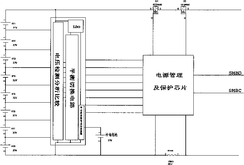
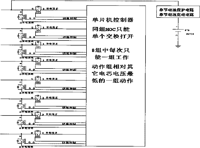
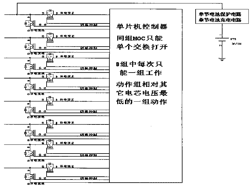
[0020] In the power battery balancing method provided by the present invention, the voltage detection analysis and comparison circuit detects the voltage of each battery unit in the battery pack in real time, and sends the detection results to the balance switching circuit and the power management and protection chip respectively; All the voltages in the detection results are compared and judged to find out that the voltage is lower than the predetermined voltage value, and the battery unit is the battery unit (cell) with the lowest voltage in the battery pack, and the supplementary battery is connected to the battery unit through the switching circuit , to supplement the battery unit, when the voltage of the battery unit reaches the average voltage or the range of the highest voltage battery, stop supplementing; the voltage detection analysis comparison circuit will conduct anot...


PUM


Abstract

The invention relates to a power battery balance charging method and a power battery balancing circuit. The circuit comprises a voltage detection, analysis and comparison circuit, a balance switching circuit, an internal constant current source circuit and a power supply management and protection chip, wherein the voltage detection, analysis and comparison circuit is used to detect the voltage of each battery unit in a battery pack in real time and to respectively transmit detection results to the balance switching circuit and the power supply management and protection chip; the balance switching circuit makes a comparison and a judgment to all voltage values to find the battery unit with the voltage which is lower than the preset voltage value and is the lowest among the voltage of all battery units in the battery pack, a compensation battery is connected with the battery unit through the switching circuit to compensate the battery unit with electricity, and the electricity compensation is stopped when the voltage of the battery unit reaches the average voltage or the highest battery voltage; and by parity of reasoning, other battery units are charged. The invention has the advantages that the compensated electricity of the battery can be accurately controlled; the compensation current is large and the efficiency is high; and the compensation conditions can be flexibly adjusted.

Description

technical field [0001] The invention relates to a power battery balancing charging method and a power battery balancing circuit. Background technique [0002] At present, the industry’s charging method for multi-string batteries generally includes two chips, one chip includes a voltage detection analysis comparison circuit, two parts of a balance switching circuit, and the other chip is a power management and protection chip. The voltage detection, analysis and comparison circuit is used to detect whether the voltage of each battery cell in the battery pack is within the allowable range. When the voltage of a certain battery cell in the battery pack is unbalanced, as long as one of the battery cells reaches the charging standard, it will be balanced. Under the control of the power management and protection chip, the switching circuit first discharges the other high-voltage battery cells in the battery pack to keep the battery in balance, so that the voltage of the entire bat...

Claims


Application Information

Patent Timeline
Patent Type & Authority Applications(China)
IPC IPC(8): H01M10/42H01M10/44H01M10/48H02J7/00
CPCY02E60/12Y02E60/10
Inventor 李武岐
Owner SUNWODA ELECTRIC VEHICLE BATTERY CO LTD
Why Eureka
Try Eureka