Devices, methods, and programs that provide vehicle guidance for power reception

一种引导装置、受电的技术,应用在电路装置、电池电路装置、电力牵引等方向,能够解决不能汽车引导、无法掌握汽车充电到什么程度的位置、不能供电侧线圈配置在适当的位置等问题

Inactive Publication Date: 2010-06-30
AISIN AW CO LTD
View PDF1 Cites 32 Cited by
  • Summary
  • Abstract
  • Description
  • Claims
  • Application Information

AI Technical Summary

Problems solved by technology

[0005] However, in the conventional charging device, when the coil on the power supply side is fixed and cannot be moved, or when the car is parked at a position where the coil on the power supply side cannot be moved, the coil on the power supply side cannot be arranged in an appropriate position, so it is necessary to correct the position of the car.
However, in the conventional charging device, it is not possible to provide guidance on how far the position of the car is suitable for charging.
Therefore, the user cannot grasp the position of the car is suitable for charging to what extent

Method used


Image

  • Devices, methods, and programs that provide vehicle guidance for power reception
  • Devices, methods, and programs that provide vehicle guidance for power reception
  • Devices, methods, and programs that provide vehicle guidance for power reception

Examples


Embodiment approach 1

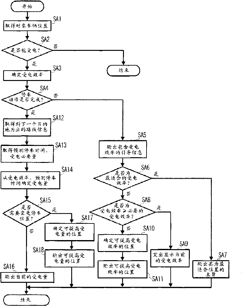
[0073] First, Embodiment 1 will be described. This method is a method of judging whether or not it is necessary to change the parking position based on a comparison between the received power received while the vehicle is parked and the required power received to be received.

[0074] (structure)

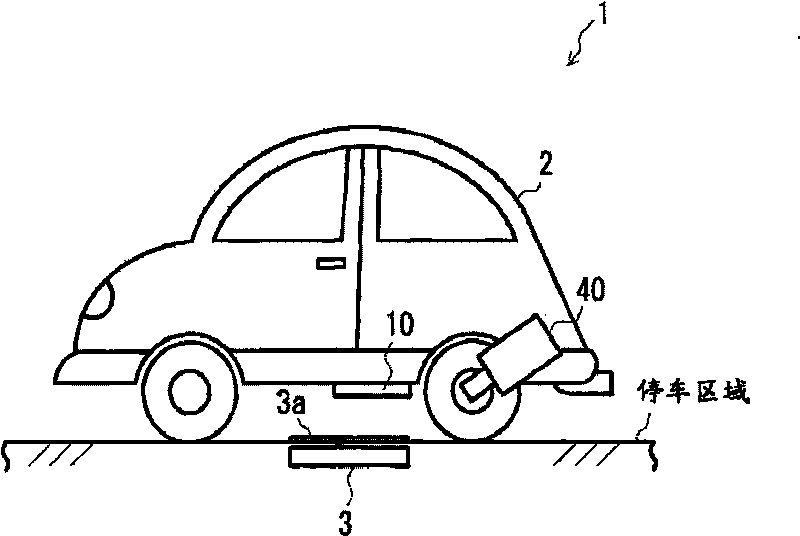
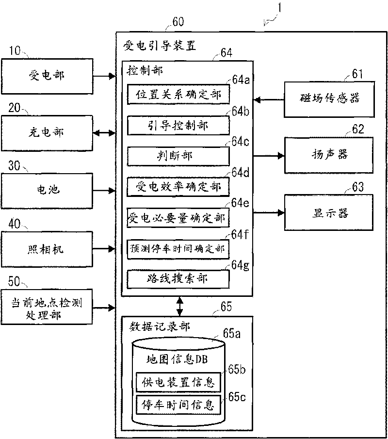
[0075] figure 1 It is a schematic diagram illustrating the power reception guidance system of Embodiment 1, figure 2 is a block diagram illustrating an example of a power receiving guidance system. This power reception guidance system 1 is a system mounted on a vehicle 2 (hereinafter referred to as "target vehicle 2" as necessary), and receives power from a power receiving mechanism installed on the vehicle 2 from a power feeding mechanism installed in a parking area. The guidance related to the non-contact power reception includes a power reception unit 10 , a charging unit 20 , a battery 30 , a camera 40 , a current location detection processing unit 50 , and a power reception...

Embodiment approach 2

[0133] Next, Embodiment 2 will be described. This method is a method of judging whether or not it is necessary to change the parking location based on a comparison between the power reception efficiency at the parking location and the required efficiency. Note that, the configuration of Embodiment 2 is substantially the same as that of Embodiment 1 unless otherwise specified, and the symbols and symbols used in Embodiment 1 are given to the configurations that are substantially the same as those of Embodiment 1 as necessary. / or the same reference numerals and / or names, and their explanations are omitted.

[0134] (deal with)

[0135] The power reception guidance process executed by the power reception guidance system 1 in the second embodiment will be described. Figure 7 This is a flowchart of the power reception boot process. In the power reception guidance process in the second embodiment, the processes from SB1 to SB13 are the same as the processes from SA1 to SA13 in ...

Embodiment approach 3

[0144] Next, Embodiment 3 will be described. This method is a method of judging whether it is necessary to change the parking position based on the power reception time required for power reception and the predicted parking time. Note that, the configuration of Embodiment 3 is substantially the same as that of Embodiment 1 unless otherwise specified, and the symbols and symbols used in Embodiment 1 are given to the configurations that are substantially the same as those of Embodiment 1 as necessary. / or the same label and / or name, the description thereof is omitted.

[0145] (deal with)

[0146]The power reception guidance process executed by the power reception guidance system 1 in Embodiment 3 will be described. Figure 8 This is a flowchart of the power reception boot process. Note that, in the power reception guidance process in the third embodiment, the processes from SC1 to SC13 are the same as the processes from SA1 to SA13 in the power reception guidance process des...


PUM


Abstract

A power reception guidance device that provides guidance pertaining to a non-contact power supply from a power supply unit (3) installed in a parking area to a power receiving unit (10) installed in a vehicle (2), comprising: a power receiving efficiency specifying unit (64d) that specifies a power receiving efficiency of the power receiving unit (10) at a current position of the vehicle (2) when a parking operation is started; and a guidance control unit (64b) that outputs through an output unit (62, 63) information pertaining to the power receiving efficiency specified by the power receiving efficiency specifying unit (64d).

Description

technical field [0001] The invention relates to a power receiving guiding device, a power receiving guiding method and a power receiving guiding program. Background technique [0002] Conventionally, there have been proposed charging devices for contactlessly charging a battery mounted on an automobile from the outside of the automobile. For example, there has been proposed a charging device in which an AC current is generated by electromagnetic induction from a power receiving coil installed in an automobile by supplying an AC current to a power feeding coil installed in a parking lot, and from the power receiving coil to the power receiving coil. Battery power supply (for example, refer to Patent Document 1). [0003] Patent Document 1: Japanese Patent Application Laid-Open No. 5-111168 (paragraphs 0010, 0011) [0004] However, in the conventional charger utilizing electromagnetic induction as described above, in order to efficiently transmit electric power from the powe...

Claims


Application Information

Patent Timeline
Patent Type & Authority Applications(China)
IPC IPC(8): H02J17/00H02J7/00
CPCB60L11/1835Y02T90/122Y02E40/72Y02T10/7088Y02T10/7005Y02T90/128B60L11/1829B60L11/1838Y02T90/14Y02T90/125B60L2250/30B60L11/182Y02T90/163B60L11/1833B60L2230/16B60L53/126B60L53/305B60L53/36B60L53/37B60L53/38B60L53/60Y02T10/70Y02T10/7072Y02T90/12Y02T90/16
Inventor 山本隆博
Owner AISIN AW CO LTD
Why Eureka
Try Eureka