Air-cooled heat dissipation structure of high-power converter device

A technology of heat dissipation structure and converter, which is applied in the direction of output power conversion device, cooling/ventilation/heating transformation, electrical components, etc. question

Inactive Publication Date: 2010-06-30
ZHEJIANG UNIV +1
View PDF4 Cites 33 Cited by
  • Summary
  • Abstract
  • Description
  • Claims
  • Application Information

AI Technical Summary

Problems solved by technology

For high-power converter devices, relying solely on this cross-flow fan cooling device obviously cannot meet the requirements
The Chinese patent number is 200410073407.3, the patent titled "A high-efficiency, low-noise radiator and improved design of common radiators", which discloses a new type of air-cooled radiator, which can increase the utilization efficiency of air volume and improve the cooling effect , but it does not fundamentally solve the problem of temperature gradient in simple lateral cooling
The Chinese patent number is 200820054320.5, and the patent titled "A Heat Dissipation Devic

Method used


Image

  • Air-cooled heat dissipation structure of high-power converter device
  • Air-cooled heat dissipation structure of high-power converter device
  • Air-cooled heat dissipation structure of high-power converter device

Examples


Embodiment

[0026] Embodiment: An air-cooled heat dissipation structure device for a high-power converter

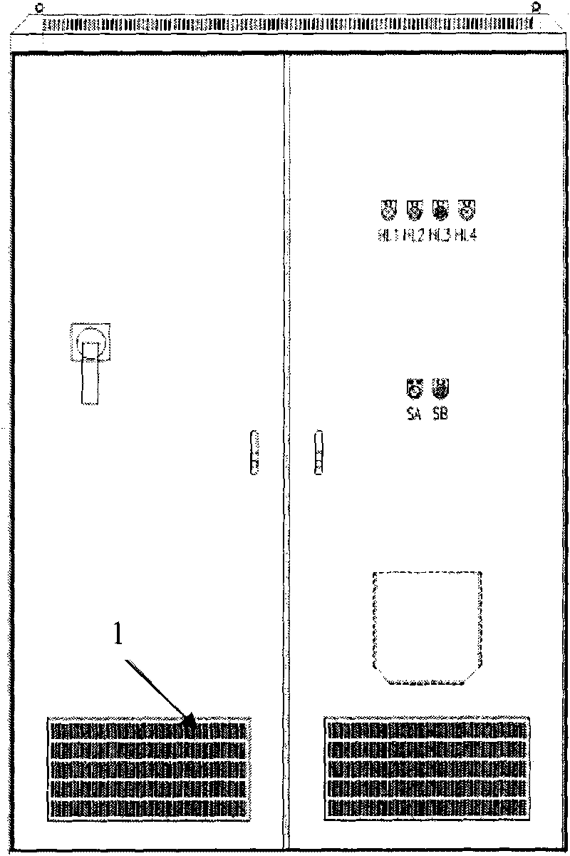
[0027] An air-cooled and heat-dissipating structure for a high-power converter device. A vertical partition is provided in the cabinet cavity of the high-power converter device, and the vertical partition separates the inner space of the cavity into a first cavity and a second cavity. Cavities; the tops of the first cavity and the second cavity are respectively provided with air outlets, and the bottoms of the first cavity and the second cavity are respectively provided with air inlets, thereby forming the first and second heat dissipation air ducts. There is a distance between the bottom edge of the vertical partition and the bottom surface of the cabinet, so as to form a connected space at the bottom of the cabinet cavity; a common air inlet is provided on the side of the connected space, and the shared air inlet is connected to the first cavity and the second cavity. The air inle...


PUM


Abstract

The invention relates to an air-cooled heat dissipation structure of a high-power converter device. In the high-power converter device, the inner space of a cavity can be partitioned into a first cavity and a second cavity by a vertical clapboard; the top parts of the first cavity and the second cavity are respectively provided with an air outlet, and the bottoms thereof are respectively provided with an air inlet, so as to form a first heat-dissipation air duct and a second heat-dissipation air duct; a power-electronic power device and a power-electronic control pat are arranged in the first heat-dissipation air duct; an auxiliary transformer, a line-side inductance, a converter-side inductance, an AC filter capacitor, a DC-side resistor and a damping resistor are sequentially distributed along the air flow direction of the second air duct; and the fist duct and the second duct are respectively provided with a fan. In the invention, various passive elements and the power-electronic power device are coordinated and unified for heat dissipation, thereby decreasing the number of the fans and reducing the volume of a heat dissipation device.

Description

technical field [0001] The invention relates to an air-cooling heat dissipation structure of a high-power converter, in particular to an air-cooling heat dissipation structure of an isolated high-power converter device. The invention is mainly used for the air-cooled heat dissipation structure of a high-power converter with many passive components, and belongs to the technical field of power electronic device manufacturing. Background technique [0002] In the industrial field, there are many heat sources in high-power power electronic devices, and these heat sources mainly come from active and passive heating elements. Active heating elements mainly refer to power electronic devices, such as thyristors, IGBTs, GTOs, and IGCTs; passive heating elements mainly include reactors, resistors, transformers, etc. All these heating elements will increase the temperature of the device, resulting in poor performance and reduced life of the components inside the device. With the deve...

Claims


Application Information

Patent Timeline
IPC IPC(8): H02M1/00H05K7/20
Inventor 陈国柱王智强谢川戴民孝戴隽文陈啸宇
Owner ZHEJIANG UNIV
Why Eureka
Try Eureka