Signal detection method having compression perception process based on orthogonal matching pursuit
An orthogonal matching tracking and compressive sensing technology, applied in baseband system components, transmission monitoring, electrical components, etc., can solve the problem of resource waste and achieve the effect of saving resources
- Summary
- Abstract
- Description
- Claims
- Application Information
AI Technical Summary
Problems solved by technology
Method used
Image

Examples
specific Embodiment approach 1
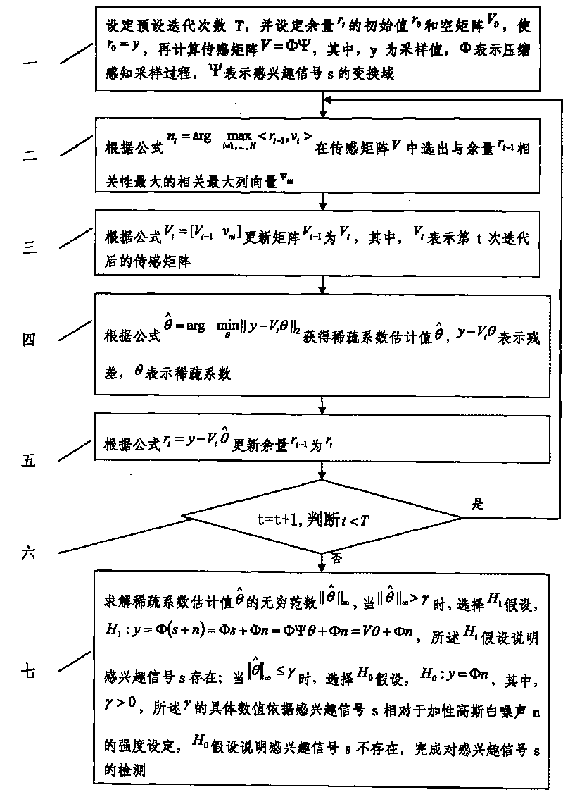
[0016] Specific implementation mode one: according to the instructions attached figure 1 Specifically illustrate this embodiment, the signal detection method with compressive sensing process based on orthogonal matching pursuit described in this embodiment, its detection process is:
[0017] Step 1: Set the preset number of iterations T, and set the margin r t The initial value of r 0 and the empty matrix V 0 , so that r 0 =y, then calculate the sensing matrix V=ΦΨ, where y is the sampling value, Φ represents the sampling process of compressed sensing, and Ψ represents the transform domain of the signal of interest s;
[0018] Step 2: According to the formula n t = arg Selected in the sensing matrix V with a margin r t-1 The most correlated most correlated column vector v nt ;
[0019] Step 3: According to the formula V t =[V t-1 v nt ] update matrix V t-1 for V t , where V t Indicates the sensing matrix after the tth iteration;
[0020] Step 4: According to th...
specific Embodiment approach 2
[0024] Specific embodiment 2: This specific embodiment is a further description of the signal detection method based on orthogonal matching pursuit with a compressed sensing process described in specific embodiment 1. According to the formula n described in step 2 of specific embodiment 1 t = arg t-1 , v i > selected in the sensing matrix V with a margin r t-1 The specific process of the most correlated column vector vnt with the greatest correlation is: find the margin r in turn t-1 and each column v in the sensing matrix V i (i=1,...,N) inner productt-1 , v i >, the column vector number corresponding to the largest inner product is n t , 1≤n t ≤N, the column vector number n t The corresponding column vector v in the sensing matrix V i chosen as the margin r in the t-th iteration t-1 The most correlated most correlated column vector v nt , where the number of iterations t is a natural number and less than the preset number of iterations T.
[0025] The detection pr...
PUM
 Abstract
Description
Claims
Application Information
 - Generate Ideas
- Intellectual Property
- Life Sciences
- Materials
- Tech Scout
- Unparalleled Data Quality
- Higher Quality Content
- 60% Fewer Hallucinations
Browse by: Latest US Patents, China's latest patents, Technical Efficacy Thesaurus, Application Domain, Technology Topic, Popular Technical Reports.
© 2025 PatSnap. All rights reserved.Legal|Privacy policy|Modern Slavery Act Transparency Statement|Sitemap|About US| Contact US: help@patsnap.com