
Ultralow temperature energy-saving lamp

An energy-saving lamp and ultra-low temperature technology, applied in lighting devices, light sources, electrical components, etc., can solve the problems of low-temperature start-up performance not being significantly improved, low-temperature start-up circuit board structure, and application limitations

Inactive Publication Date: 2010-06-30
王庆利
View PDF2 Cites 0 Cited by
  • Summary
  • Abstract
  • Description
  • Claims
  • Application Information

AI Technical Summary

Problems solved by technology

Its disadvantage is that due to the harsh working temperature of the ballast and starter itself, it cannot work in a low temperature or even ultra-low temperature environment (for example, below -30°C), which makes the fluorescent lamp unable to start and ignite, making this type of energy-saving lamp The application in cold regions is greatly limited; at the same time, because the ignition process often needs to go through many jumps to achieve stable light, this jump process will also greatly damage the service life of the lamp
[0003] The invention application with application number 200820048853.2 discloses an energy-saving lamp that can be started in a low-temperature environment. It uses an electrodeless light source and a low-temperature start-up circuit board to realize the low-temperature start-up of the electrodeless lamp, but the structure of the low-temperature start-up circuit board is complicated and does not Applicable to energy-saving lamps other than electrodeless lamps; the invention application with application number 97246253.8 discloses a long-life energy-saving lamp, which uses a push-pull oscillating circuit to ensure stable operation of the energy-saving lamp and prolong its service life, but its low-temperature start-up performance has not been significantly improved improve

Method used


Image

  • Ultralow temperature energy-saving lamp
  • Ultralow temperature energy-saving lamp
  • Ultralow temperature energy-saving lamp

Examples


Embodiment Construction

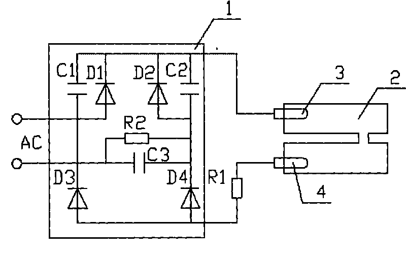
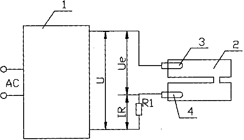
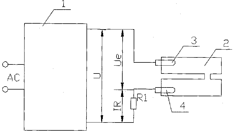
[0018] Attached below figure 1 Illustrate the working principle of the present invention: the electronic starter circuit 1 is composed of four diodes D 1 ~D 4 and two diodes C 1 、C 2 Composed of voltage doubler rectifier circuit, C 3 Used to control the working current of the lamp tube. When an AC power source (preferred voltage is 220V) is connected, the voltage doubler rectifier circuit converts the AC power into a DC power to generate a higher potential, so that two poles 3 and 4 A high potential difference is generated between them, forming an arc discharge. Connect a selected resistor R in series between the lamp tube 2 and the electronic starter circuit 1 1 , whose purpose is to change the negative characteristics of the voltage and current characteristics of the lamp discharge circuit into positive characteristics. When the lamp tube is lit, the discharge can reach a stable condition. Resistance R 2 Is the discharge resistor, used to discharge the capacitor C a...


PUM


Abstract

The invention relates to an electronic energy-saving lamp belonging to the technical field of energy-saving lamps, in particular to an energy-saving lamp which can be normally started in an ultralow temperature environment. The electronic energy-saving lamp is characterized by adopting an electronic starter instead of an original inducting type ballast and a starter on a fluorescent lamp tube, the one-step rapid start can be realized, and the service life of the lamp tube is prolonged; the energy-saving lamp has wide application range of voltage and can be normally started in a low temperature and even ultralow temperature environment; and compared with a common incandescent lamp, the power factor is greatly improved, and the electric energy is saved.

Description

technical field [0001] The invention relates to an ultra-low temperature energy-saving lamp, which can be applied to various occasions under low temperature or even ultra-low temperature environments, and belongs to the technical field of energy-saving lamps. Background technique [0002] Energy-saving fluorescent lamps sold in the existing market are usually ignited by induction ballasts and starters. Its disadvantage is that due to the harsh working temperature of the ballast and starter itself, it cannot work in a low temperature or even ultra-low temperature environment (for example, below -30°C), which makes the fluorescent lamp unable to start and ignite, making this type of energy-saving lamp The application in cold regions is greatly limited; at the same time, because the ignition process often needs to go through many jumps to achieve stable light emission, this jump process will also greatly damage the service life of the lamp tube. [0003] The invention applicat...

Claims


Application Information

Patent Timeline
IPC IPC(8): H05B41/14H05B41/282
Inventor 王庆利
Owner 王庆利
Learn More