
Engine lubricating oil pressure state monitoring and protection system

Active Publication Date: 2018-07-13
LONCIN MOTOR
View PDF6 Cites 0 Cited by
  • Summary
  • Abstract
  • Description
  • Claims
  • Application Information

AI Technical Summary

Problems solved by technology

The engine can run normally when the oil level is higher than the limit level of the oil sensor, but if the oil pump leaks or the lubricating oil channel is blocked, the engine crankshaft and other key lubricating parts cannot form an oil film or the oil film ruptures due to the low oil pressure, which will cause engine lubrication. Bad and locked, engine damage occurs

Method used


Image

  • Engine lubricating oil pressure state monitoring and protection system
  • Engine lubricating oil pressure state monitoring and protection system

Examples


Embodiment Construction

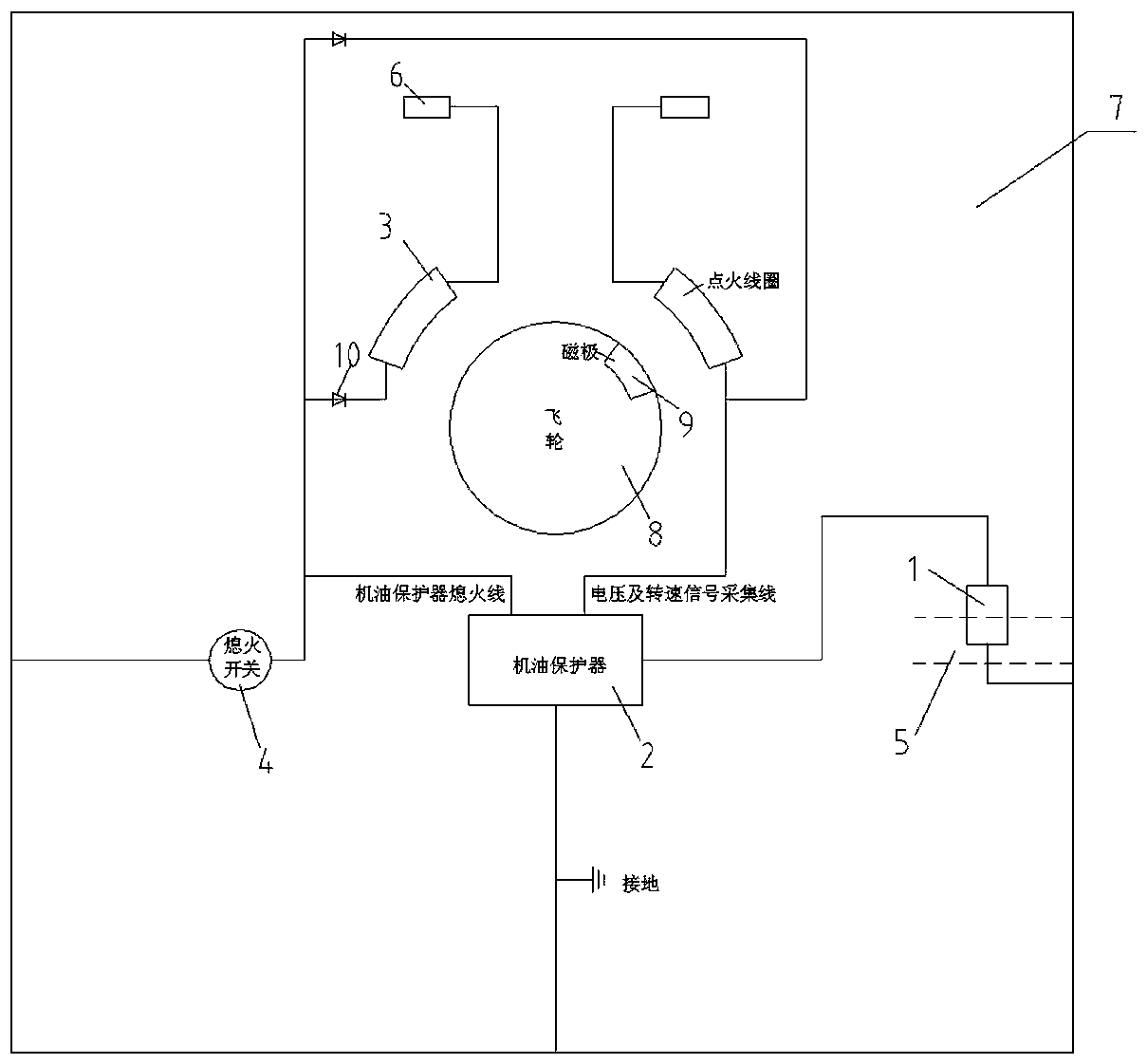
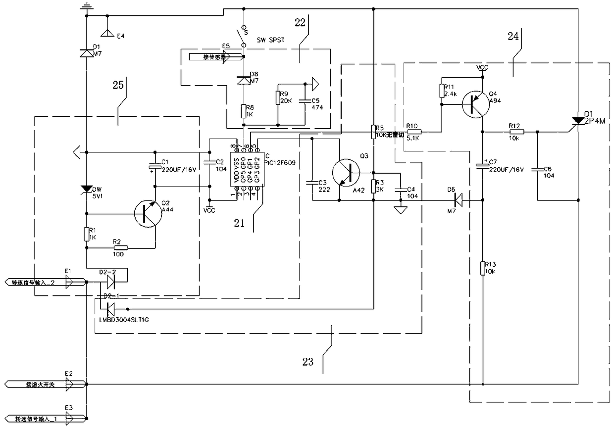
[0015] see figure 1 and figure 2 , an engine lubricating oil pressure state monitoring protection system, comprising a pressure sensor 1, an oil protector 2 and at least two igniters. The pressure sensor 1 is used to monitor the pressure of the main lubricating oil gallery 5 of the engine. A one-way isolation diode 10 is provided between each igniter and the flameout switch 4, which is used to prevent mutual igniting between several igniters and affect the normal ignition of the engine 7. There are two igniters in this embodiment, corresponding to the twin-cylinder engine 7 . The ignition coil 3 secondary of each igniter is electrically connected with each spark plug 6 respectively, and the ignition coil 3 primary of each igniter is respectively correspondingly connected with the negative pole of the one-way isolation diode 10, and the positive pole of each one-way isolation diode 10 is all connected with the flame-out switch 4 The other end of the flameout switch 4 is con...


PUM


Abstract

The invention relates to an engine lubricating oil pressure state monitoring and protection system, comprising a pressure sensor, an oil protector and at least two igniters, each igniter and a flameout switch are provided with a one-way isolation diode, and the ignition coil of each igniter The secondary is electrically connected to the spark plug respectively, and the primary of the ignition coil of each igniter is respectively connected to the negative pole of the one-way isolation diode, and the positive pole of each one-way isolation diode is connected to one end of the flame-off switch, and the other end of the flame-off switch is grounded, and the engine oil protection The device is used to collect the engine speed signal and the oil pressure signal, and the oil protector is used to receive the engine speed signal and the oil pressure signal, compare the engine speed signal with the speed setting value, compare the engine oil pressure signal with the pressure setting value, and use Control engine flameout and shutdown. It can ensure that the engine will not be locked and damaged by moving parts such as the engine crankshaft due to lack of engine oil or too low lubricating oil pressure or poor lubrication.

Description

technical field [0001] The invention relates to an engine protection device, in particular to an engine lubricating oil pressure state monitoring and protection system. Background technique [0002] When the engine is working, many transmission parts make high-speed relative motion in a small gap, such as crankshaft main journal and main bearing, crank pin and connecting rod bearing, cam journal and cam bearing, piston, piston ring and cylinder wall , each movement pair of the gas distribution mechanism and the transmission gear pair, etc. Although the working surfaces of these parts are finely machined, they are uneven when viewed under magnification. If these surfaces are not lubricated, intense friction will occur between them. The dry friction between the metal surfaces not only increases the power consumption of the engine and accelerates the wear of the working surface of the parts, but also may burn the working surfaces of the parts due to the heat generated by the ...

Claims


Application Information

Patent Timeline
Patent Type & Authority Patents(China)
IPC IPC(8): F01M1/22
Inventor 杨松刘兵冯朋博鲁卡成勇龚兴明张正华何飞
Owner LONCIN MOTOR
Learn More