Circuit of light-adjustable ballast with fluorescent tube resistance feedback network

A technology of resistance feedback and ballast, which is applied in the field of dimmable ballast circuit, can solve the problems that fluorescent lamps are difficult to work normally and cannot be ignited, and achieve the effect of normal igniting, working and reliable operation

Inactive Publication Date: 2009-08-05
SELF ELECTRONICS CO LTD
View PDF8 Cites 0 Cited by
  • Summary
  • Abstract
  • Description
  • Claims
  • Application Information

AI Technical Summary

Problems solved by technology

In this way, under normal circumstances, fluorescent lamps using this circuit can work normally, but in the darkest setting of the dimmer and in a low-temperature environment (below 5°C), it is difficult for fluorescent lamps using this circuit to work normally, and even cannot be ignited

Method used


Image

  • Circuit of light-adjustable ballast with fluorescent tube resistance feedback network

Examples


Embodiment Construction

[0009] The present invention will be described in further detail below in conjunction with the embodiments of the drawings.

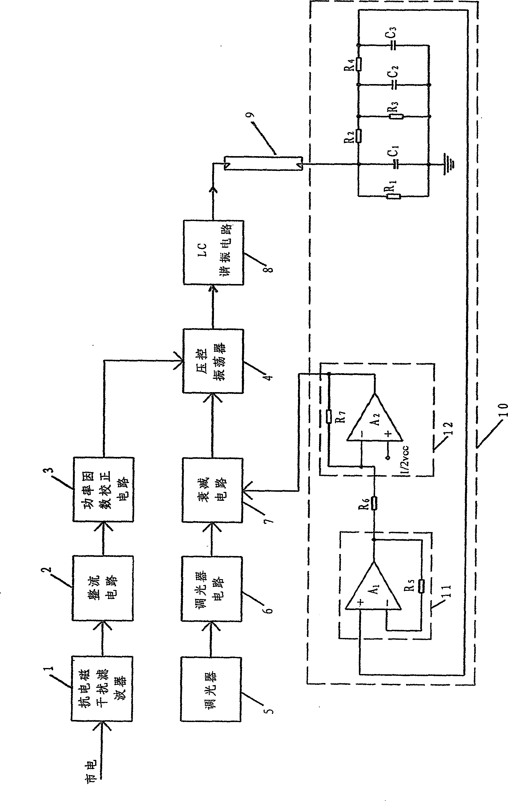
[0010] Such as figure 1 As shown, a dimmable ballast circuit with a lamp resistance feedback network includes an anti-electromagnetic interference filter 1, a rectifier circuit 2, a power factor correction circuit 3, which are sequentially connected to a voltage controlled oscillator 4; a dimmer 5 Connect the dimming circuit 6 to the voltage-controlled oscillator 4 via the attenuation circuit 7; the voltage-controlled oscillator 4 is connected to the lamp tube 9 via the LC resonance circuit 8; the lamp tube 9 is also connected to the lamp tube resistance feedback network 10.

[0011] The lamp resistance feedback network 10 includes a capacitor C1 connected in parallel with a resistor R1 and attenuated by resistors R2 and R3, connected to a π-type filter composed of resistors R4, capacitors C2, and C3, and then connected to the operation in the isolation sta...


PUM


Abstract

The invention discloses a dimmable ballast circuit with a lamp tube resistance feedback network, comprising an anti-electromagnetic interference filter (1), a rectification circuit (2), and a power factor correction circuit (3), which are sequentially connected to a voltage control circuit The oscillator (4); the dimmer (5) is connected to the dimming circuit (6) and then connected to the voltage-controlled oscillator (4) through the attenuation circuit (7); the voltage-controlled oscillator (4) is then connected to the LC resonant circuit (8 ) is connected to the lamp tube (9); the other end of the lamp tube (9) is also connected with a lamp tube resistance feedback network (10). The advantage of the present invention is that it overcomes the defect that fluorescent lamps in the prior art cannot work normally under the darkest setting of the dimmer and low temperature environment (below 5°C), so that the fluorescent lamp using this circuit can be used even when the setting of the dimmer is the lowest. It can also be ignited normally and work reliably in dark and low temperature environments (around 0°C).

Description

Technical field [0001] The invention relates to a dimmable ballast circuit, in particular to a dimmable ballast circuit with a lamp tube resistance feedback network. Background technique [0002] The existing dimmable ballast circuit usually includes an anti-electromagnetic interference filter, a rectifier circuit, and a power factor correction circuit, which are sequentially connected to a voltage-controlled oscillator; the dimmer is connected to the dimming circuit and is connected to the voltage-controlled oscillator after the attenuation circuit The voltage controlled oscillator is connected to the lamp tube through the LC resonant circuit. In this way, under normal circumstances, the fluorescent lamp using this circuit can work normally, but in the darkest and low temperature environment (below 5℃) with the dimmer, it is difficult for the fluorescent lamp using this circuit to work normally, or even unable to ignite . Summary of the invention [0003] The technical problem ...

Claims


Application Information

Patent Timeline
Patent Type & Authority Patents(China)
IPC IPC(8): H05B41/14H05B41/16
Inventor 周智白
Owner SELF ELECTRONICS CO LTD
Why Eureka
Try Eureka