Electromagnetic wave measuring apparatus

A measuring device and electromagnetic wave technology, applied to measuring devices, electrical components, measuring electrical variables, etc., can solve problems such as time-consuming and low operating efficiency

Inactive Publication Date: 2010-06-30
MURATA MFG CO LTD
View PDF2 Cites 8 Cited by
  • Summary
  • Abstract
  • Description
  • Claims
  • Application Information

AI Technical Summary

Problems solved by technology

Therefore, it takes a lot of time to prepare before the measurement, and there is a problem of low work efficiency.

Method used


Image

  • Electromagnetic wave measuring apparatus
  • Electromagnetic wave measuring apparatus
  • Electromagnetic wave measuring apparatus

Examples


Embodiment Construction

[0044] The electromagnetic wave measurement device according to the embodiment of the present invention will be described in detail below with reference to the drawings.

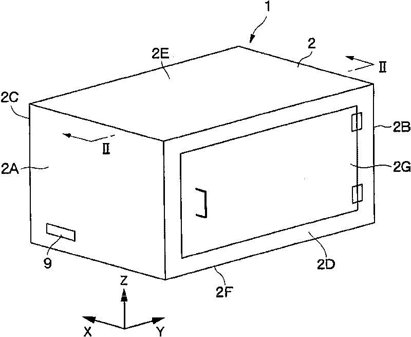
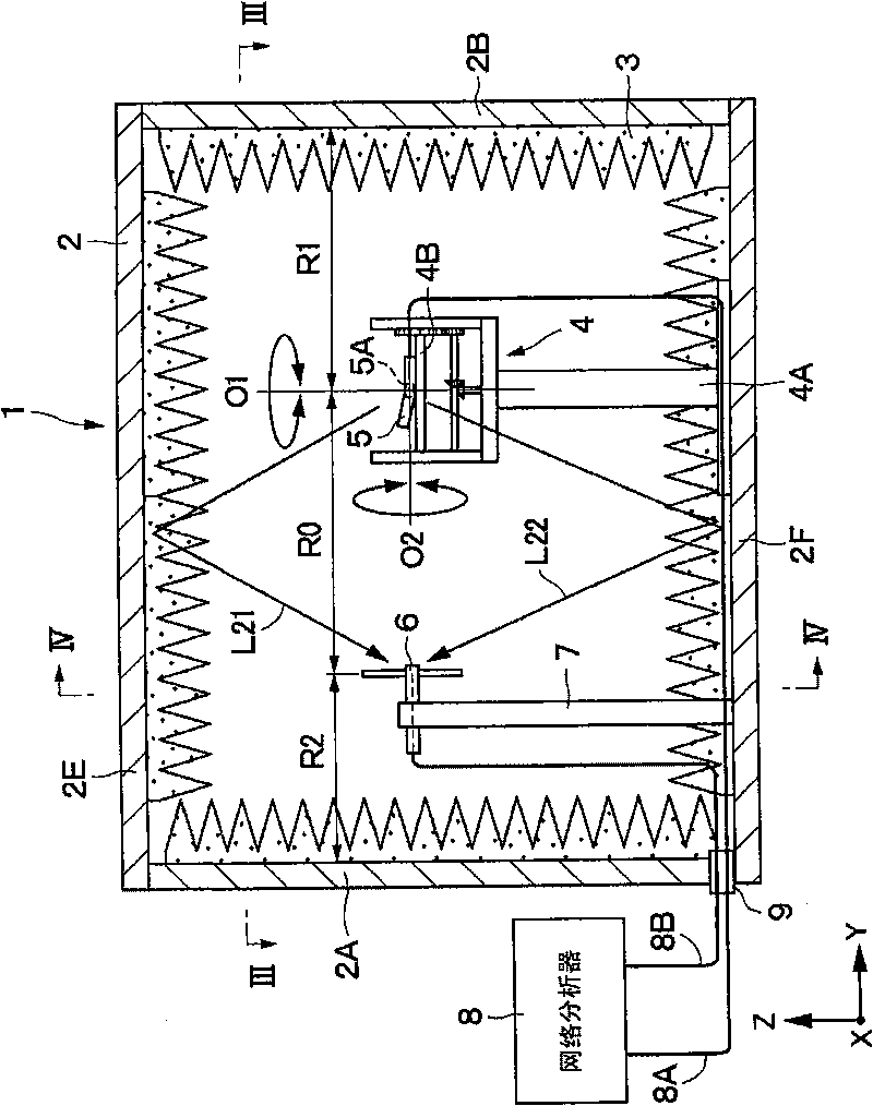
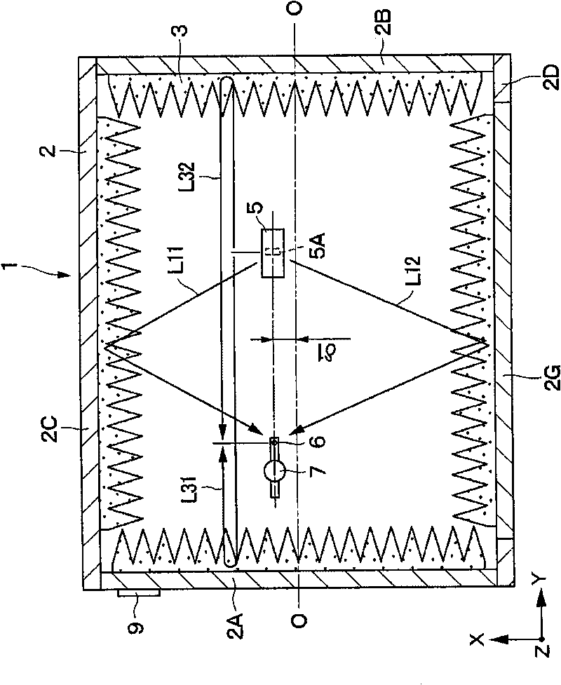
[0045] exist Figure 1 to Figure 4 Among them, the radio wave anechoic box 1 is composed of a metal case 2 formed in a box shape using an aluminum plate with a thickness of, for example, about 1 to 2 mm, and a radio wave absorber 3 provided inside the metal case 2 . In addition, the radio anechoic box 1 can not only block electromagnetic waves from outside, but also prevent reflection of electromagnetic waves inside.

[0046] Here, the metal case 2 is formed to have a length of about 50 to 100 cm in the width direction (X direction), the axial direction (Y direction), and the height direction (Z direction), for example. The metal case 2 has a front wall 2A and a rear wall 2B on both sides in the axial direction, a left wall 2C and a right wall 2D on both sides in the width direction, and a top 2E and a bottom...


PUM


Abstract

A radio anechoic box (1) is formed by arranging a radio wave absorber (3) inside a metallic case (2). An object (5) to be measured and a measuring antenna (6) are arranged apart from each other along an axial direction inside the box (1). The object (5) and the antenna (6) are placed offset from the center (O) of a cross section of the radio anechoic box (1) based on a wavelength lambda of electromagnetic waves in a frequency band where the absorber (3) exhibits lower absorption characteristics. Thus, a plurality of reflection waves traveling from the object (5) to the measuring antenna (6) can be interfered and canceled to reduce influence of the reflection waves.

Description

technical field [0001] The present invention relates to an electromagnetic wave measuring device used for measuring electromagnetic waves radiated by, for example, mobile phones. Background technique [0002] Generally, as far as the electromagnetic wave measurement device is concerned, it is known to arrange the measured object such as a mobile phone in a small radio anechoic box, and to measure the radiation efficiency of the antenna installed on the measured object (for example, refer to Patent Document 1 ,2). Also, Patent Document 1 discloses that a radio wave absorbing sheet used in a specific frequency band is provided inside the radio wave anechoic box in order to provide a small and inexpensive measurement space. In this case, the radio wave absorbing sheet has radio wave absorption characteristics in the electromagnetic wave measurement frequency band. Therefore, it is configured to use different radio wave absorbing sheets depending on the frequency band used by ...

Claims


Application Information

Patent Timeline
Patent Type & Authority Applications(China)
IPC IPC(8): G01R29/10H05K9/00
CPCG01R29/0821
Inventor 北田浩志山本幸雄
Owner MURATA MFG CO LTD
Why Eureka
Try Eureka