Tube rolling mill balanced device

A technology of balancing device and tube rolling mill, which is applied in the direction of metal rolling stand, metal rolling mill stand, metal rolling, etc., can solve the problems of complicated equipment, and achieve the effect of convenient installation and increased degree of freedom.

Inactive Publication Date: 2010-07-07
TAIYUAN HEAVY IND
View PDF0 Cites 4 Cited by
  • Summary
  • Abstract
  • Description
  • Claims
  • Application Information

AI Technical Summary

Problems solved by technology

In order to achieve this purpose, the current pipe rolling mill has to use another mechanism

Method used


Image

  • Tube rolling mill balanced device
  • Tube rolling mill balanced device
  • Tube rolling mill balanced device

Examples


Embodiment Construction

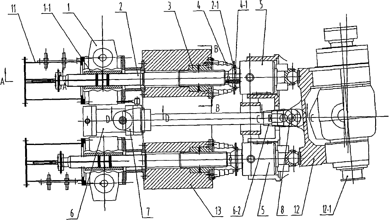
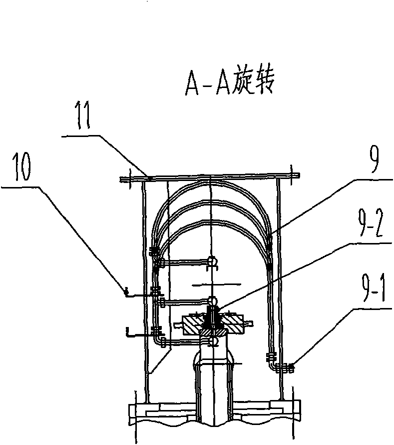
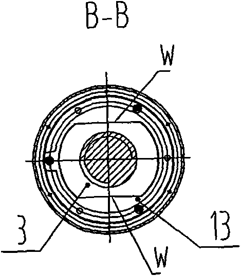
[0016] Such as figure 1 , 2 , 3, 4, and 5, a pipe mill balance device is composed of a pressing transmission device 1, a lead screw 2, a nut 3, a telescopic cover 4, a quick opening cylinder 5, a balance cylinder 6, a cylinder support 7, a pin Shaft 8, lubricating pipeline 9, electric control element 10, protective cover 11, roll box 12 and so on. The worm wheel 1-1 of the worm gear reducer is an internal spline, which cooperates with the spline body at one end of the lead screw 2. When the transmission device 1 is pressed down to rotate, due to the action of the spline, the lead screw 2 will rotate and allow Its axial linear movement; the other end of the screw 2 is a zigzag thread, which cooperates with the zigzag thread of the inner hole of the nut 3. When the screw 2 rotates, due to the effect of the screw thread, the screw 2 rotates while Axial linear movement; the balance oil cylinder 6 is installed in the middle of the two lead screws 2, and the cylinder body of the b...


PUM


Abstract

The present invention discloses a tube rolling mill balanced device, which relates to a steal rolling machine. The present invention solves the problem that the existing tube rolling mill balanced device only can get rid of gaps of guide screws, and can not enable rollers to rapidly lift up. The present invention is characterized in that a balanced oil cylinder 6 is arranged at the middle of two guide screws 2; a cylinder body of the balanced oil cylinder 6 is beyond the outer part of a machine frame 13; a cylinder body ear shaft 6-1 of the balanced oil cylinder 6 is hinged with an oil cylinder support 7 fixed on the machine frame 13; a piston ear ring 6-2 of the balanced oil cylinder 6 is hinged with the middle of a roller box 12; a roller 12-1 is arranged in the roller box 12; and the two guide screws 2 are respectively linked with both ends of the roller box 12 through two quick-opening cylinders 5.

Description

technical field [0001] The invention belongs to steel rolling machines, in particular to a balancing device for lifting rolls of a pipe rolling machine. Background technique [0002] The current rolling mill in the production of seamless steel pipes needs to balance the gravity of the rolls when adjusting the opening of the rolls, and eliminate the mechanical clearance of the adjusting screw, and then lock it. This kind of mechanical equipment is called rolling tubes. Machine balance device. [0003] Current pipe mill balancing device (see figure 1 ) includes: pressing down transmission device 1, leading screw 2, balance oil cylinder 6, described pressing down transmission device 1 is to utilize two worm gear reducers to drive two leading screws to lift, and two leading screws are connected to rollers 12- On the two bearing seats of 1, the balance oil cylinder 6 is connected in parallel on both sides of the lead screw 2 to eliminate the mechanical gap caused by the gravity...

Claims


Application Information

Patent Timeline
IPC IPC(8): B21B31/20B21B28/00
Inventor 张良夫
Owner TAIYUAN HEAVY IND
Why Eureka
Try Eureka