Pneumatic piston sewage valve

A pneumatic piston, sewage technology, applied in the direction of lift valve, valve details, valve device, etc., can solve the problems of slow closing speed, can not be used normally, valve leakage, etc., to achieve the effect of fast closing speed

Inactive Publication Date: 2010-07-07
SHANDONG SHUANGLUN
View PDF0 Cites 1 Cited by
  • Summary
  • Abstract
  • Description
  • Claims
  • Application Information

AI Technical Summary

Problems solved by technology

[0003] The technical problem solved by the present invention is to solve the problem that the existing pneumatic sewage valve cannot meet the requirement of high-speed flow of sewage, the valve is easily stuck by impurities in the sewage and leaks, the closing speed is slow, and the high-speed instantaneous passing and cutting of sewage cannot be realized. The problem that the occasions that require fast and frequent opening and closing cannot be used normally. Provide a valve that can meet the requirements of high-speed flow of sewage. The valve is not easy to be stuck by impurities in the sewage and cause leakage. The closing speed is fast, and the high-speed instant passing and cutting of sewage can be realized. , a pneumatic piston sewage valve that can be used normally in occasions that require rapid and frequent opening and closing

Method used


Image

  • Pneumatic piston sewage valve
  • Pneumatic piston sewage valve

Examples


Embodiment Construction

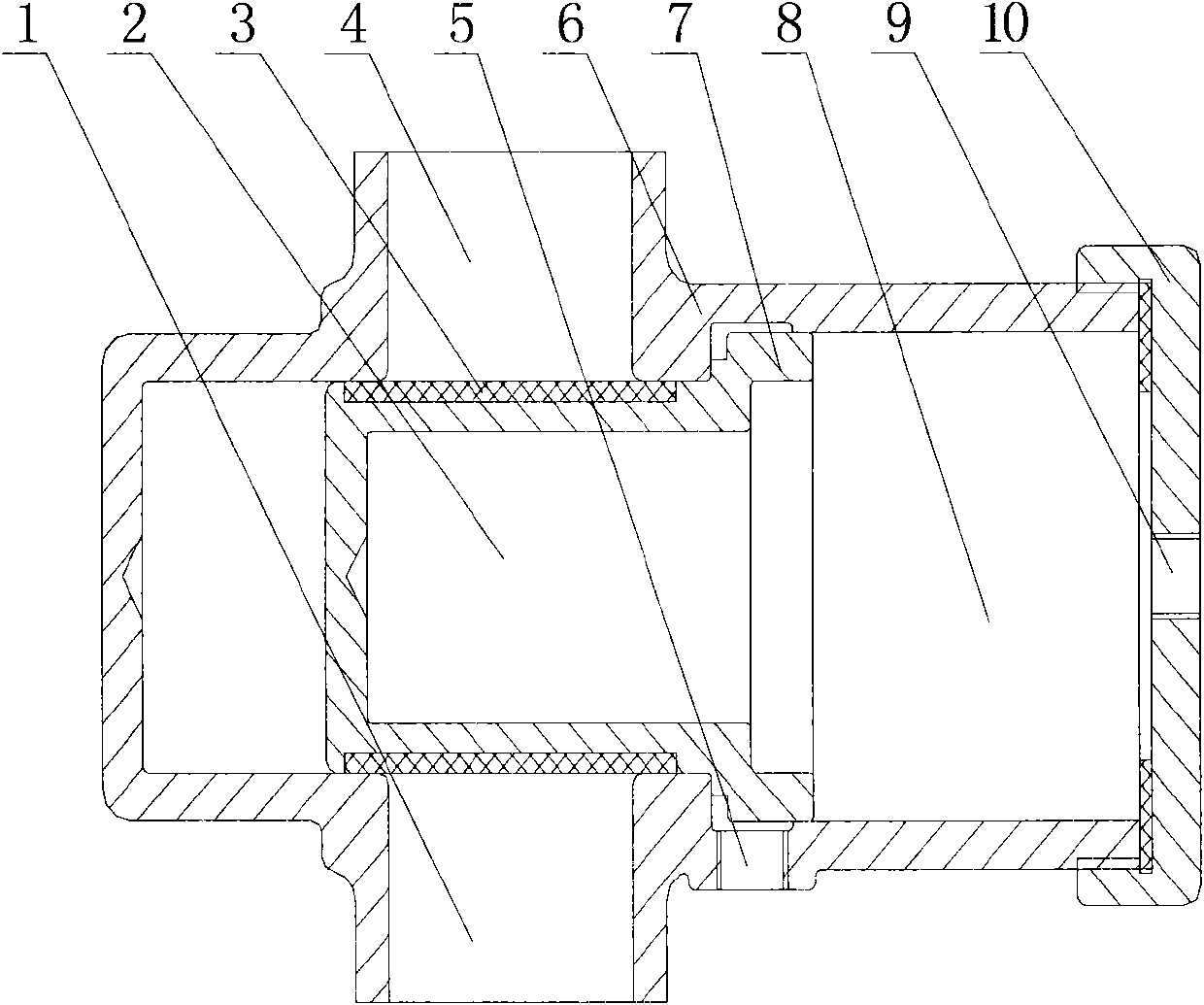
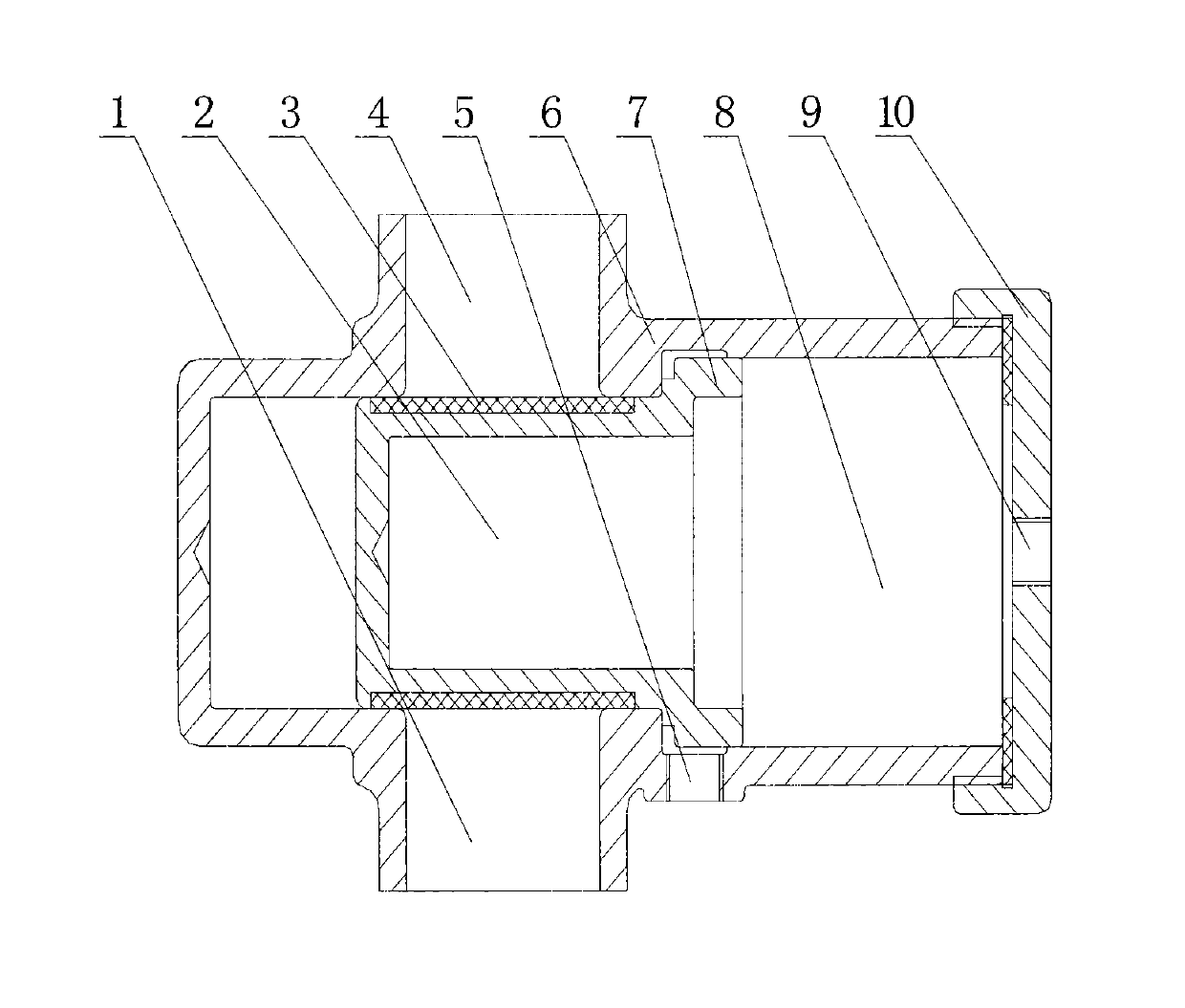
[0010] As shown in the figure, the pneumatic piston sewage valve is provided with a valve body 6. The valve body 6 is provided with a sewage inlet 1 and an outlet 4. There is a straight-through flow channel between the inlet 1 and the outlet 4. The inside of the valve body 6 is connected to the flow channel. A piston chamber 8 is intersected, and a piston 2 is arranged in the piston chamber 8. The diameter of the piston 2 is larger than the diameter of the flow channel, and the flow channel can be blocked when the piston 2 passes through the flow channel. The piston 2 is provided with a sealing sleeve 3, which can enhance the sealing performance between the piston 2 and the flow channel. The rear end of the piston 2 is provided with a stepped spacer ring 7, the piston chamber 8 on both sides of the spacer ring 7 is provided with control ports 5, 9, and the rear end of the piston chamber 8 is provided with an end cover 10 for easy installation. As can be seen from the figure, t...


PUM


Abstract

The invention relates to a pneumatic sewage valve, in particular to a pneumatic piston sewage valve which is provided with a valve body. A sewage inlet and a sewage outlet are arranged on the valve body. A through runner is arranged between the sewage inlet and the sewage outlet. A piston chamber intersecting with the runner is arranged in the valve body. A piston is arranged in the piston chamber. The diameter of the piston is larger than the diameter of the runner. A step-shaped spacer ring is arranged at the rear end of the piston. Control ports are arranged on the piston chamber on the two sides of the spacer ring. Since the through runner is arranged between the sewage inlet and the sewage outlet, the requirement of high-speed sewage flow is satisfied; and since the piston chamber intersecting with the runner is arranged in the valve body, the piston is arranged in the piston chamber, the diameter of the piston is larger than the diameter of the runner, the step-shaped spacer ring is arranged at the rear end of the piston and the control ports are arranged on the piston chamber on the two sides of the spacer ring, the valve is not apt to be blocked by impurities in sewage, leakage is not apt to occur, the closing speed is fast, the high-speed instant passage and cut-off of the sewage can be realized, the valve can be used normally in places requiring the valve to be opened and closed rapidly and frequently, and the valve is suitable for sewage discharge.

Description

technical field [0001] The invention relates to a pneumatic sewage valve, in particular to a pneumatic piston sewage valve. Background technique [0002] We know that the inlet and outlet of the existing pneumatic sewage valves are often not straight through, and the internal passage is always diverted to the side to discharge air, which cannot meet the requirements of high-speed flow of sewage; and pneumatic butterfly valves, ball valves, etc. have baffles in the middle, and the valves are easy to discharge. Leakage occurs due to being stuck by impurities in the sewage, and the closing speed of this type of pneumatic valve is slow, which cannot realize the high-speed and instantaneous passing and cutting of sewage, and cannot be used normally in occasions that require rapid and frequent opening and closing. Contents of the invention [0003] The technical problem solved by the present invention is to solve the problem that the existing pneumatic sewage valve cannot meet t...

Claims


Application Information

Patent Timeline
Patent Type & Authority Applications(China)
IPC IPC(8): F16K1/00F16K31/122
Inventor 刘元成胡建军邹存海
Owner SHANDONG SHUANGLUN
Why Eureka
Try Eureka