Supercharge Your Innovation With Domain-Expert AI Agents!

Multifunctional valve

A multi-functional valve and valve body technology, applied in the direction of functional valve type, valve details, safety valve, etc., can solve the problems of high cost, inconvenient daily operation of operators, inaccurate dosing amount, etc.

Active Publication Date: 2010-07-07
ZHEJIANG AILIPU TECH
View PDF0 Cites 6 Cited by
  • Summary
  • Abstract
  • Description
  • Claims
  • Application Information

AI Technical Summary

Problems solved by technology

[0002] In the pharmaceutical, chemical, food, water treatment and other industries, in the process of mixing liquid and liquid in a certain proportion or quantitative dosing of liquid and mixing of solid medicine, in order to prevent pipelines and pumps from bursting and other damage due to artificial or accidental blockage (if cast Adding flammable, explosive or highly toxic liquids will have more serious consequences), generally a safety valve must be installed, the function of the safety valve is when the pipeline pressure exceeds a certain pressure The liquid automatically pushes away the spring, and flows back through the bypass for pressure relief to protect the pipeline and the pump; in order to detect the composition or quality of the liquid in the dosing pipeline, so that measures can be taken in time to solve the problem, sampling must be set at a suitable position Valve, when the pump is just started, due to the large amount of air in the pipeline, the dosage will be inaccurate, and some liquid medicine will chemically react with the air, so it is generally considered to set an exhaust valve in the pipeline to allow the liquid to pass through The air is compressed to discharge the air from the exhaust valve; the setting of many valves and bypasses in the pipeline brings great inconvenience to the installation and maintenance of the pipeline, and at the same time the cost is also high, which also brings great inconvenience to the daily operation of the operator. great inconvenience

Method used


Image

  • Multifunctional valve
  • Multifunctional valve
  • Multifunctional valve

Examples


Embodiment Construction

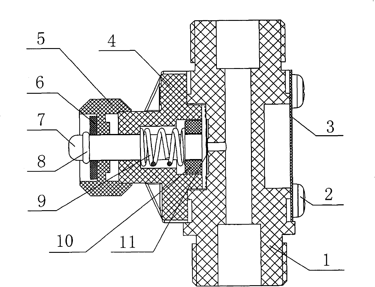
[0017] Below in conjunction with accompanying drawing, the present invention will be further described:

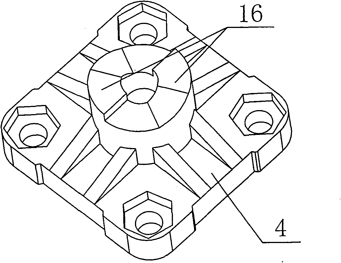
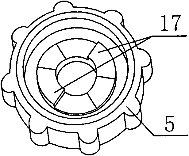
[0018] As shown in the figure, a multifunctional valve includes a valve body 1. The valve body 1 and the valve control assembly are screwed together through bolts 2. A decorative film 3 is provided on the other side of the valve body 1. The valve control assembly includes a valve Cover 4, diaphragm 11, diaphragm connecting rod 7, spring 9 and valve handle 5, said diaphragm 11 is glued to one end of diaphragm connecting rod 7, and the other end of diaphragm connecting rod 7 is sleeved with spring 9 and connected to The bonnet 4 is threaded and matched, and a spring adjustment block 10 can also be set at one end of the diaphragm connecting rod 7 to be socketed and matched with the spring 9. One end passing through the bonnet 4 is movably connected with the valve handle 5, specifically, the diaphragm is connected Rod 7 passes through one end of the valve cover 4 to set a groo...


PUM


Abstract

The present invention relates to a multifunctional valve. The multifunctional valve comprises a valve body; the multifunctional valve is characterized in that the valve body is in screw match with a valve control assembly through a bolt; the valve control assembly includes a valve cover, a membrane, a membrane connecting rod, a spring and a valve handle; the membrane is hinged on one end of the membrane connecting rod; the other end of the membrane connecting rod is sleeved on the spring and then perforated on the valve cover; one end penetrating through the valve cover of the membrane connecting rod is movably connected with the valve handle. The multifunctional valve integrates safety valves, sampling valves and air discharge valves into one, which realizes functions needed by liquid adding pipeline of user and greatly reduces installment and maintenance difficulty of pipeline; simultaneously, the valve is simple and convenient in operation, and low in cost; the valve is specifically suitable for liquor adding pipeline of middle and high pressure and low flow rate.

Description

technical field [0001] The invention relates to a multifunctional valve. Background technique [0002] In the pharmaceutical, chemical, food, water treatment and other industries, in the process of mixing liquid and liquid in a certain proportion or quantitative dosing of liquid and mixing of solid medicine, in order to prevent pipelines and pumps from bursting and other damage due to artificial or accidental blockage (if cast Adding flammable, explosive or highly toxic liquids will have more serious consequences), generally a safety valve must be installed, the function of the safety valve is when the pipeline pressure exceeds a certain pressure The liquid automatically pushes away the spring, and flows back through the bypass for pressure relief to protect the pipeline and the pump; in order to detect the composition or quality of the liquid in the dosing pipeline, so that measures can be taken in time to solve the problem, sampling must be set at a suitable position Valv...

Claims


Application Information

Patent Timeline
Patent Type & Authority Applications(China)
IPC IPC(8): F16K31/60F16K17/06
Inventor 罗献尧
Owner ZHEJIANG AILIPU TECH
Features
  • R&D
  • Intellectual Property
  • Life Sciences
  • Materials
  • Tech Scout
  • Unparalleled Data Quality
  • Higher Quality Content
  • 60% Fewer Hallucinations
Learn More