Dynamic impact loading test bed and test system thereof

A loading test and dynamic technology, applied in measuring devices, instruments, scientific instruments, etc., can solve the problems of poor safety performance and bulky equipment, and achieve the effect of low noise pollution, high energy conversion rate, and easy repeated test.

Inactive Publication Date: 2010-07-07
BEIJING INSTITUTE OF TECHNOLOGYGY
View PDF8 Cites 32 Cited by
  • Summary
  • Abstract
  • Description
  • Claims
  • Application Information

AI Technical Summary

Benefits of technology

This new testing platform uses specialized components that can help reduce vibrations during shocks caused by external forces on equipment or vehicles while they are being tested for their effectiveness. It achieves this through adding extra resilient bouncing back into its structure when it're hit with something like another object. By doing so, these platforms allow faster acceleration without causing excessive strain on sensitive parts inside them. Additionally, there has been developed technology called TL (tension-spring) units which convert kinetic energy from linear movement into rotational motion instead of converting it directly into electricity. These technologies make sure everything goes smoothly even if some things get stuck between moving elements quickly enough.

Problems solved by technology

Technological Problem addressed in this patents relates to improving the performance of shock load tests machines while reducing their size due to factors such as reduced space requirements and lower costs associated therewith. Current methods involve dropping weights onto specific areas of material being tested before it reaches its final destination. These current solutions have limitations because they require either complex machining processes or specialized tools like air guns or laser systems.

Method used


Image

  • Dynamic impact loading test bed and test system thereof
  • Dynamic impact loading test bed and test system thereof
  • Dynamic impact loading test bed and test system thereof

Examples


Embodiment Construction

[0026] The specific embodiment of the present invention will be further described in detail below in conjunction with the accompanying drawings. For those skilled in the art, the above objects, features and advantages of the present invention will be apparent from the detailed description of the present invention.

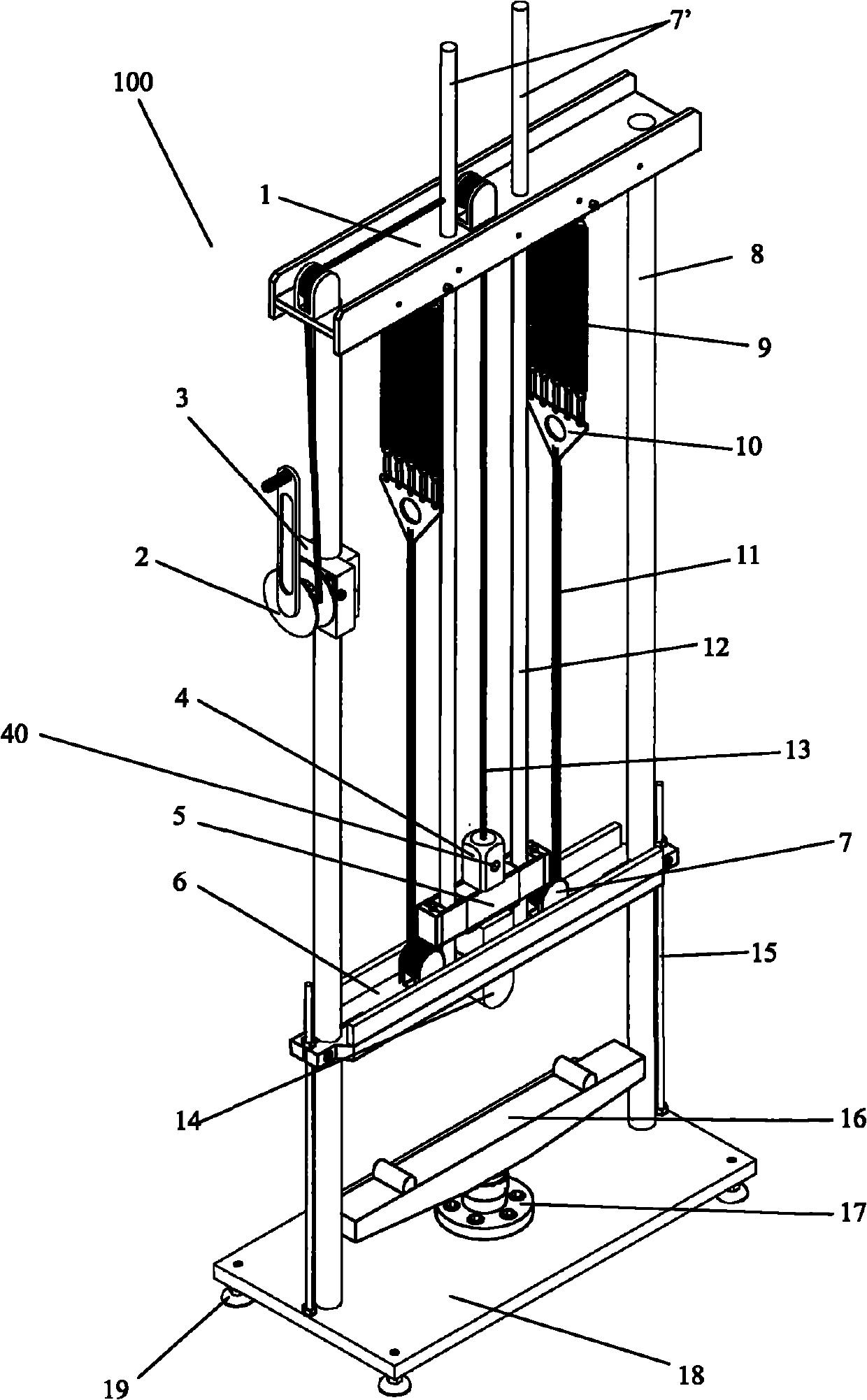
[0027] refer to figure 1 , is a schematic diagram of the overall structure of a dynamic impact loading test bench according to a specific embodiment of the present invention. As shown in the figure, the dynamic impact loading test bench 100 includes an impact unit, a tension spring unit, a lifting unit and a specimen carrying platform carried on a fixed frame.

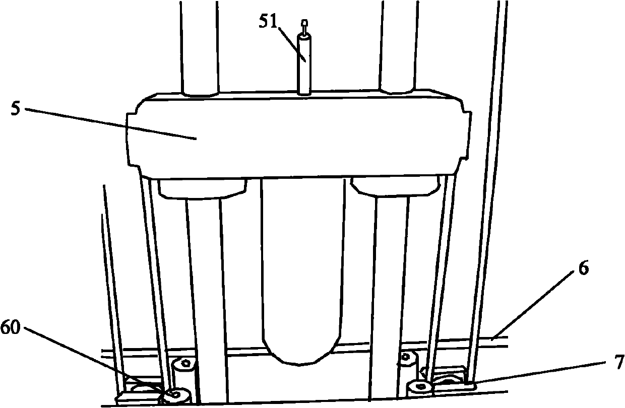
[0028] exist figure 1 Among them, the impact unit is a T-shaped heavy hammer, which includes a hammer body 5 forming a body and a hammer head 14 forming a striking part. The hammer body 5 is coated with a nylon sleeve, which is used to reduce the friction with the "I"-shaped adjustment horizontal plate 6...


PUM


Abstract

The invention discloses dynamic impact loading test bed and a test system thereof. The dynamic impact loading test bed comprises an impact unit, a lifting unit and a test piece plummer, wherein the impact unit is carried on a fixed rack and is connected with a tension spring unit; and the tension spring unit can exert an elastic restoring force on the impact unit. The dynamic impact loading test system comprises the dynamic impact loading test bed and tests the mechanical property of a test piece to be tested by connecting with a computer. The dynamic impact loading test bed and the system exert extra downward elastic restoring force on the impact unit by the tension spring unit, can still obtain higher impact loading speed under the precondition of realizing device miniaturization and has the functions and advantages of high energy conversion rate, little noise pollution, stable emission, easy speed regulation, convenient test repetition, and the like.

Description


Claims


Application Information

Patent Timeline
Owner BEIJING INSTITUTE OF TECHNOLOGYGY
Why Eureka
Try Eureka