Recording power compensating system and method

A power compensation and power technology, which is applied in the field of programming power compensation system, can solve problems such as unmaintainable recording quality, errors, and programming failures.

Inactive Publication Date: 2010-07-07
QUANTA STORAGE INC
View PDF0 Cites 1 Cited by
  • Summary
  • Abstract
  • Description
  • Claims
  • Application Information

AI Technical Summary

Problems solved by technology

However, the database needs to test all existing CD drives and CDs, and the construction work is too complicated
And new brands and new types of CD players or CDs are constantly appearing, and old models and CDs cannot be used immediately
In addition, even for the same brand and type of optical disc drives or optical discs, due to errors in manufacturing process, assembly, materials or uniformity, the characteristics of individual optical disc drives or optical discs will vary, and the pre-stored data cannot be applied to allow the recording of recordings. The quality cannot be maintained at a certain level, and even cannot be read, resulting in burning failure

Method used


Image

  • Recording power compensating system and method
  • Recording power compensating system and method
  • Recording power compensating system and method

Examples


Embodiment Construction

[0037] In order to achieve the above object, the present invention adopts the technical means and its effects, hereby give preferred embodiments, and illustrate as follows in conjunction with the accompanying drawings.

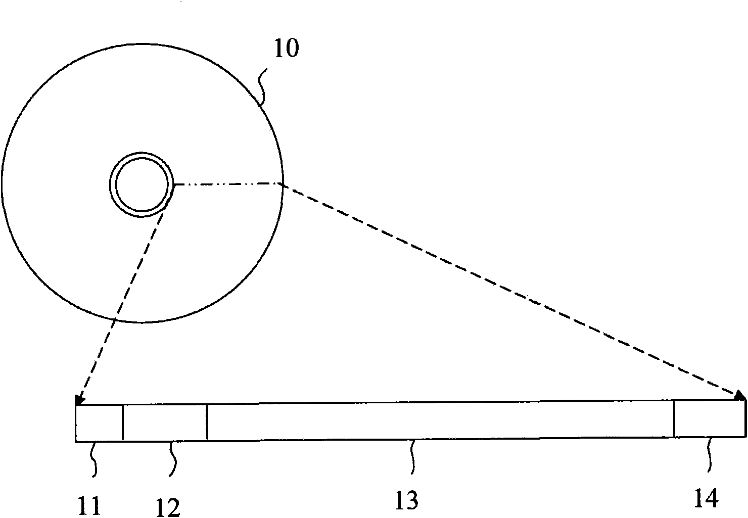
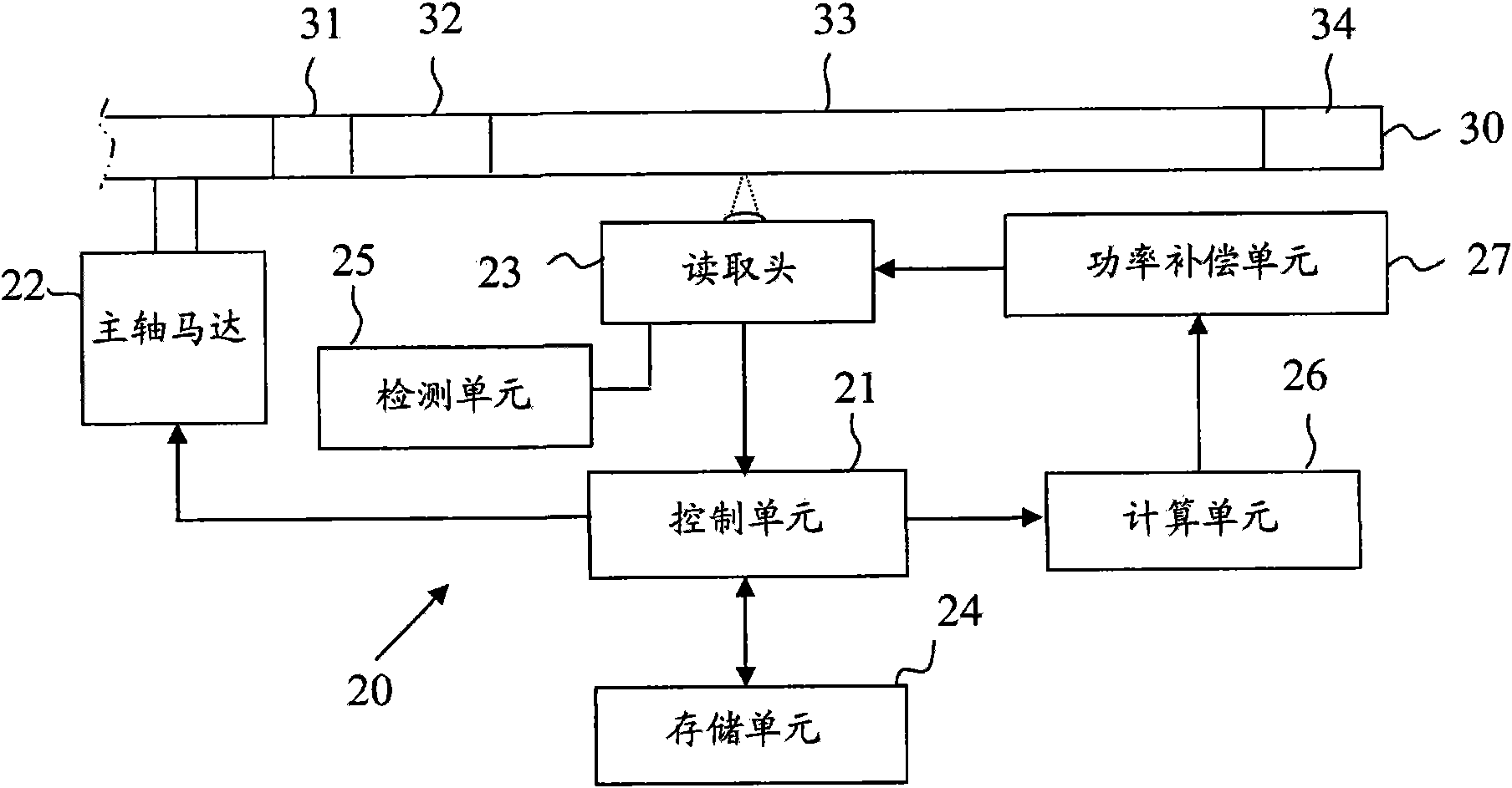
[0038] Please refer to figure 2 , is a functional block diagram of the programming power compensation system of the present invention. figure 2 It shows that the programming power compensation system 20 of the present invention includes a control unit 21 , a spindle motor 22 , a read head 23 , a storage unit 24 , a detection unit 25 , a calculation unit 26 , and a power compensation unit 27 . The control unit 21 is a microprocessor for controlling the spindle motor 22 to rotate an optical disc 30 . The optical disc 30 is a recordable optical disc, including a test area 31 , a lead-in area 32 , a user data area 33 and a lead-out area 34 from the inner circle to the outer circle. The control unit 21 also controls the read head 23 to project a laser beam onto...


PUM


Abstract

The invention relates to a recording power compensating system and a recording power compensating method. A best power test is controlled by a control unit; a calculating unit is used for approximating test power and a corresponding asymmetry parameter into a linear test power function and calculating a difference value of the asymmetry parameter tested by a test unit and corresponding power compensation amount; and a power compensating unit makes use of the power compensation amount to adjust laser beam power so as to improve the recording quality.

Description

technical field [0001] The invention relates to a recording power compensation system and method, in particular to a system and method for maintaining the recording quality by using the compensation power when an optical disc drive is recording with the power of the best power test. Background technique [0002] Recordable optical discs generally irradiate the laser beam emitted by the reading head to form marks such as pits or phase deformations on the optical disc, and use the difference in the amount of reflected light between marked and unmarked to form digital signals of 0 and 1 to achieve Purpose of recording data. The power of the laser beam needs to maintain a certain level of reflected light of the mark on the disc. Too much or insufficient power will affect the depth and shape of the mark, change the light reflection of the mark, and make it difficult to recognize the difference in the reflected light between marked and non-marked , so that it cannot be read and t...

Claims


Application Information

Patent Timeline
IPC IPC(8): G11B7/125G11B7/004G11B7/1267
Inventor 黄朝群黄识忠
Owner QUANTA STORAGE INC
Why Eureka
Try Eureka