Electric connector

A technology for electrical connectors and connecting parts, which is applied in the directions of connection, fixed connection, and two-component connection device, can solve the problems of high crosstalk and affect the signal transmission quality of electrical connectors, and achieves reduction of crosstalk, improvement of signal transmission quality, and increased The effect of the masking effect

Active Publication Date: 2010-07-07
FOXCONN (KUNSHAN) COMPUTER CONNECTOR CO LTD +1
View PDF1 Cites 30 Cited by
  • Summary
  • Abstract
  • Description
  • Claims
  • Application Information

AI Technical Summary

Problems solved by technology

[0003] A commonly used technology for reducing crosstalk is to set ground terminals between adjacent signal terminals, such as an electrical connector disclosed in Chinese Invention Patent Publication No. 1937324A, which is used to transmit high-frequency digital signals , which includes an insulating body, a conductive terminal and a shielding shell covering the insulating body. The insulating body includes a base and a tongue protruding forward from the base. Each conductive terminal includes a contact portion arranged on the surface of the tongue and an extension All the welding parts are arranged in a row, and the conductive terminals include ground terminals and several pairs of differential signal terminals. However, there is only one ground connection between the welding parts of two adjacent pairs of differential signal terminals of the electrical connector. The welding part of the terminal makes the crosstalk between two adjacent pairs of differential signal terminals still high, which affects the signal transmission quality of the electrical connector

Method used


Image

  • Electric connector
  • Electric connector
  • Electric connector

Examples


Embodiment Construction

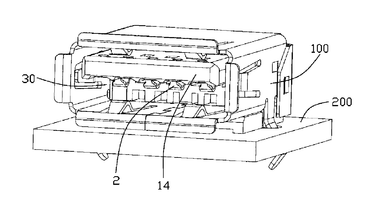
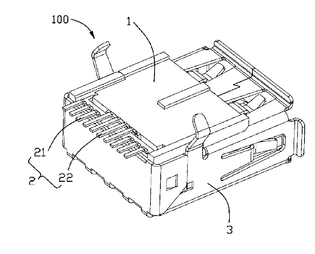
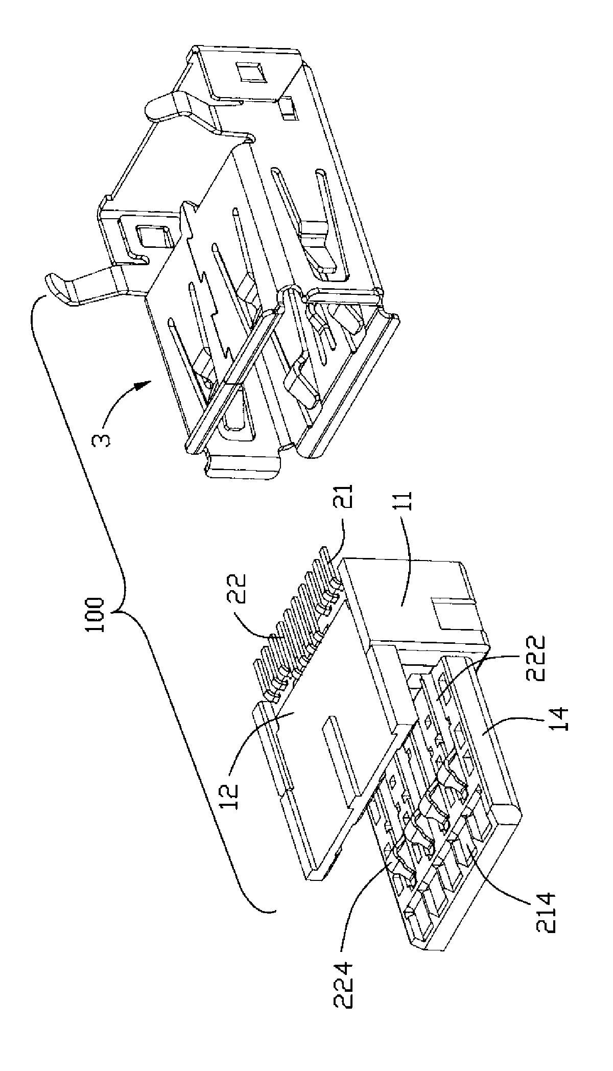
[0015] see Figure 1 to Figure 7 As shown, the electrical connector 100 of the present invention is a USB receptacle connector, which is used to be installed on the circuit board 200 for insertion of a USB 2.0A type docking plug and a USB 3.0A type docking plug (not shown), which includes: an insulating body 1. A plurality of conductive terminals 2 provided on the insulating body 1 and a metal shielding shell 3 covering the insulating body 1 .

[0016] The insulating body 1 includes a first body 11 and a second body 12 fixed on the bottom of the first body 11 . The first body 11 includes a first base portion 13 and a tongue 14 protruding forward from the first base portion 13. The first base portion 13 includes a rear end portion 131 and two side portions respectively extending forward from the left and right ends of the rear end portion 131. 132 and the accommodation groove 133 recessed between the rear end portion 131 and the two side portions 132, the accommodation groove ...


PUM


Abstract

The invention discloses an electric connector, comprising an insulating body and a conductive terminal arranged on the insulating body. The conductive terminals comprise a plurality of grounded terminals and a plurality of pairs of differential signal terminals, wherein each grounded terminal is provided with a first welding part extending out of the insulating body, each differential signal terminal is provided with a second welding part extending out of the insulating body, and the first, second and third welding parts are arranged into one row, and the first welding part of two grounded terminals is arranged between the second welding parts adjacent to the two pairs of differential signal terminals, thereby the shielding effect between the two adjacent pairs of differential signal terminals is increased, the crosstalk between the differential signal terminals is reduced, and the signal transmission quality of the electric connector is improved.

Description

【Technical field】 [0001] The invention relates to an electrical connector, in particular to an electrical connector with differential signal transmission. 【Background technique】 [0002] Electrical connectors provide signal connections between electronic devices using conductive terminals. Typically, the conductive terminals are closely spaced such that "crosstalk" occurs between adjacent conductive terminals. The mixed electric fields cause crosstalk when one conductive terminal induces electrical interference in adjacent conductive terminals, thereby compromising signal integrity. With the miniaturization and high speed of electronic devices, high signal integrity electrical communication becomes more common and the reduction of this crosstalk becomes an important factor in connector design. [0003] A commonly used technology for reducing crosstalk is to set ground terminals between adjacent signal terminals, such as an electrical connector disclosed in Chinese Inventio...

Claims


Application Information

Patent Timeline
Patent Type & Authority Applications(China)
IPC IPC(8): H01R24/16H01R12/32H01R13/11H01R24/76H01R12/55
Inventor 何家勇郑启升
Owner FOXCONN (KUNSHAN) COMPUTER CONNECTOR CO LTD
Why Eureka
Try Eureka