Auxiliary lifting mechanism of presser foot of computerized embroidery machine

An embroidery machine and presser foot technology, which is applied to the embroidery machine mechanism, embroidery machine, cloth press mechanism and other directions, can solve the problems of large rotation noise of the cam mechanism, poor synchronization of movement coordination, inconvenient assembly and maintenance, etc., and achieves low production cost. , good stability and simple structure

Inactive Publication Date: 2010-07-14
冯品牛
View PDF1 Cites 18 Cited by
  • Summary
  • Abstract
  • Description
  • Claims
  • Application Information

AI Technical Summary

Problems solved by technology

[0004] In order to overcome the above-mentioned shortcomings, the purpose of the present invention is to provide a computerized embroidery machine presser foot auxiliary lifting mechanism with three links instead of a cam mechanism, so that it can solve the problem of using a cam mechanism in the existing computerized embroidery machine presser foot auxiliary lifting mechanism. Lifting the presser foot will cause the cam mechanism to rotate noisy, poor synchronization of movement, instability, easy damage, inconvenient assembly and maintenance, and high production costs. The purpose is to achieve the following technical solutions

Method used


Image

  • Auxiliary lifting mechanism of presser foot of computerized embroidery machine
  • Auxiliary lifting mechanism of presser foot of computerized embroidery machine
  • Auxiliary lifting mechanism of presser foot of computerized embroidery machine

Examples


Embodiment Construction

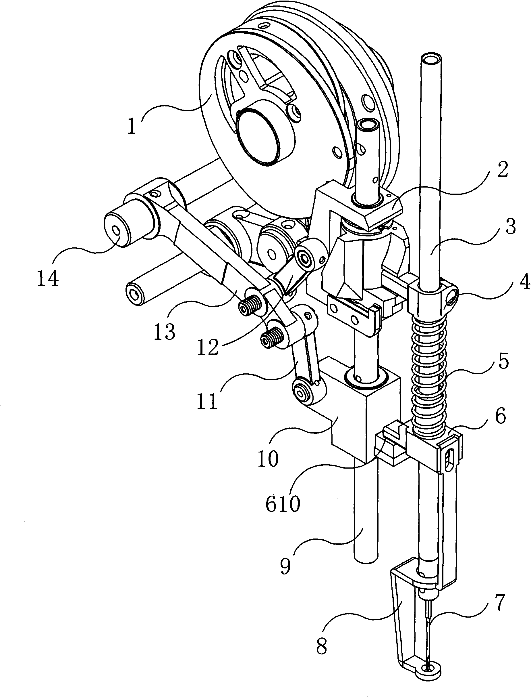
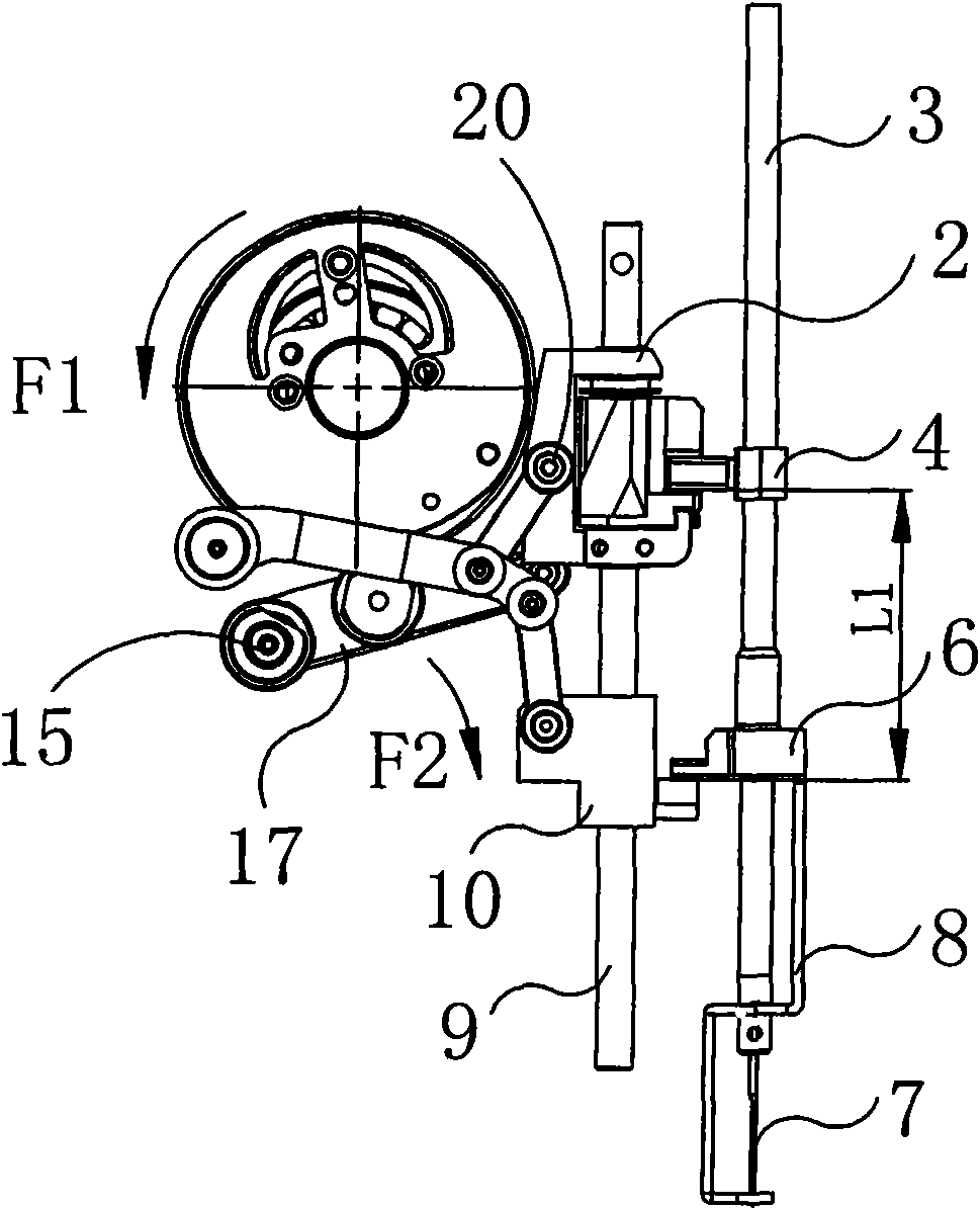
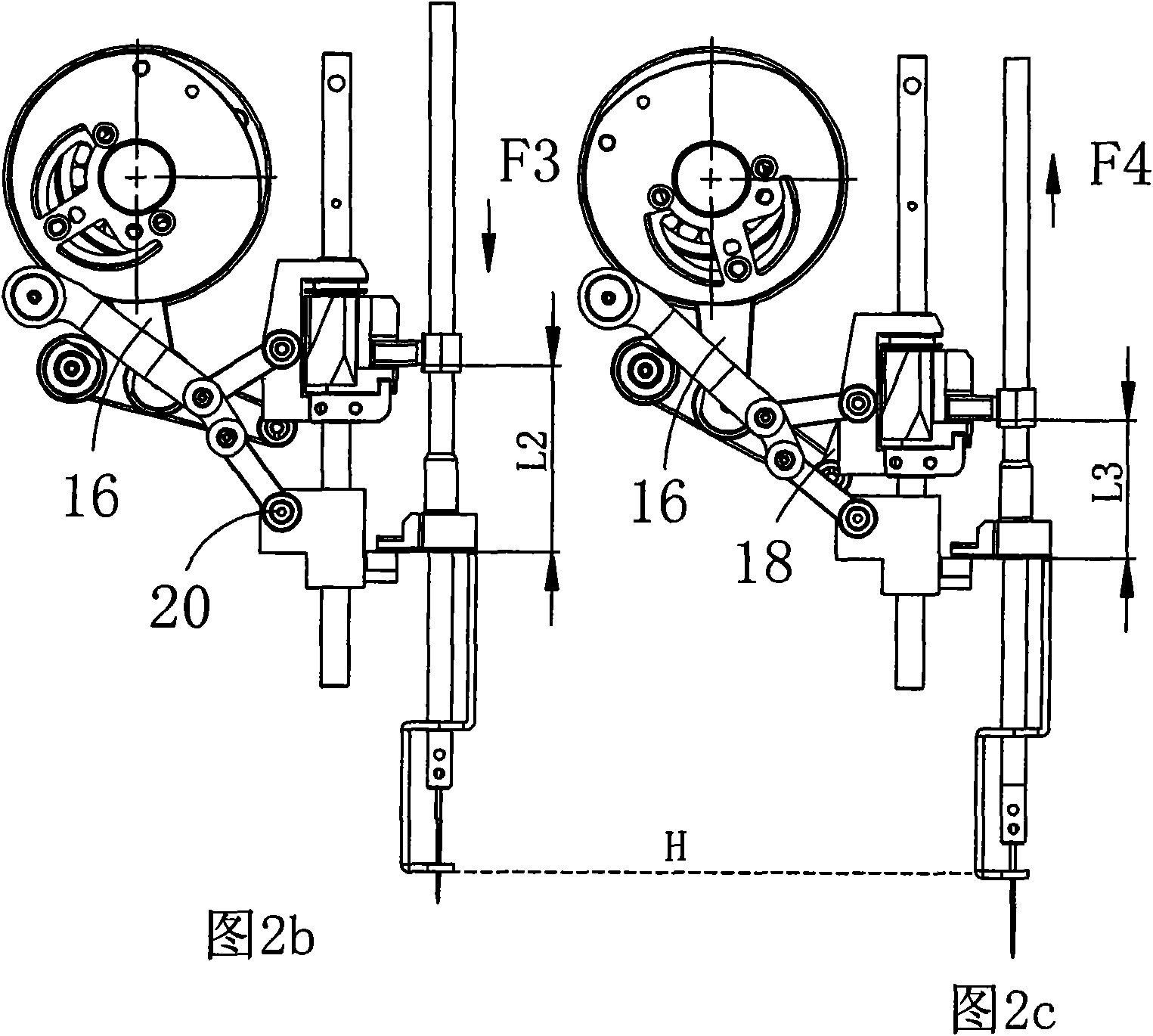
[0023] Now in conjunction with accompanying drawing, structure of the present invention, motion principle and use are further described. Such as Figure 1~6 As shown, the presser foot auxiliary lifting mechanism (or E mechanism) is mainly composed of three-hole connecting rod A13, two-hole connecting rod B12, two-hole connecting rod C11 and related pin shaft 19 to form a "Y"-shaped connecting rod mechanism. The other parts belong to the relevant parts of the computerized embroidery machine. Such as figure 1 As shown, the relevant component structures are as follows:

[0024] One end of the needle bar 3 is provided with a needle 7 and a presser foot 8, as well as a driving block 4 and a transmission block 6. The guide bar 9 is provided with a slider A2 and a slider B10. A spring 5 is arranged between the driving block and the transmission block, and the driving block is fixed. on the needle bar. The slider A is connected to one side of the driving block through a groove, an...


PUM


Abstract

The invention relates to an auxiliary lifting mechanism of a presser foot of a computerized embroidery machine, which is designed aiming at the technical problem of poor structure of the auxiliary lifting mechanism (a cam mechanism) of the presser foot of the computerized embroidery machine. A link mechanism adopting three connecting rods is arranged in the auxiliary lifting mechanism of the presser foot and is in a Y shape, one end of the link mechanism is fixed in a casing of a machine head by a shaft A, and the other two ends are respectively fixed at a slide block A and a slide block B. In a group of link mechanism comprising a three-hole connecting rod A, a two-hole connecting rod B and a two-hole connecting rod C, the three-hole connecting rod A is bent in an arc shape; and a hole C1 of the three-hole connecting rod A is connected with a hole A2 of the two-hole connecting rod B by a pin shaft, and a hole A1 of the three-hole connecting rod A is connected with a hole A3 of the two-hole connecting rod C by a pin shaft. The invention has high running accuracy, small noise, convenient maintenance, assembly and use, good movement matching synchronism and stability, low production cost and extensive application range and is suitable for a high-speed computerized embroidery machine and similar tailoring equipment.

Description

technical field [0001] The invention relates to a computerized embroidery machine, in particular to an auxiliary lifting mechanism for a presser foot of a computerized embroidery machine. Background technique [0002] Embroidery machine, also known as embroidery machine, is a sewing machine used for embroidery. The working method of traditional mechanical embroidery machine is: replace the sewing machine with a bottom plate with a small round hole, the needle keeps going in and out, and then use the hand-held embroidery frame, Hold the cloth taut. However, with the introduction of electronic technology into the field of sewing machines in 1975, the functional characteristics of embroidery were added to the computerized sewing machine, and the mechanical embroidery machine entered the era of computer-controlled mechatronics from mechanical control. Based on the microprocessor, these computerized embroidery machines make appropriate changes to the software and hardware of the...

Claims


Application Information

Patent Timeline
Patent Type & Authority Applications(China)
IPC IPC(8): D05C11/06D05B29/02D05B55/14
Inventor 冯品牛
Owner 冯品牛
Why Eureka
Try Eureka