
Anti-theft lock core with multi-gear marble structure and application thereof

A technology of anti-theft lock cylinder and tumbler lock cylinder, which is applied in the application of locks, cylinder pin locks, building locks, etc., and can solve problems such as high labor intensity, inconsistency in the name of mechanical anti-theft locks, and reduced security of locks.

Active Publication Date: 2010-07-14
靖江市悦达安防设备有限公司
View PDF5 Cites 5 Cited by
  • Summary
  • Abstract
  • Description
  • Claims
  • Application Information

AI Technical Summary

Problems solved by technology

Of these three structural locks, the flat key lock was first invented, and the pins were designed to be in three to five gears. Later, in order to prevent theft and improve the security of the lock, a cross key lock and a sleeve key lock were invented. The pins of the cross key lock were designed to be six. There are seven gears, and the sleeve key lock pins are designed to be seven gears. The number of pins is increased, which improves the security. However, the number of lock cylinder pins is too many, which will bring many quality problems to the manufacturing. The most annoying thing in the lock industry is the pins. Hole drilling process, because the hole is drilled on the outer circle of the lock cylinder, at present, the hole is still drilled manually on a drilling machine, which is labor-intensive. The problem of the coaxiality of the upper and lower marble holes has not been effectively solved. Quality problems are dealt with by enlarging the chamfer and hole diameter. The result is that the hole diameter is too large. Confidentiality
"Currently the theft is serious, the mechanical anti-theft lock has become famous but not true, the current situation is very grim

Method used


Image

  • Anti-theft lock core with multi-gear marble structure and application thereof
  • Anti-theft lock core with multi-gear marble structure and application thereof
  • Anti-theft lock core with multi-gear marble structure and application thereof

Examples


Embodiment Construction

[0009] The present invention will be further described below in conjunction with accompanying drawing:

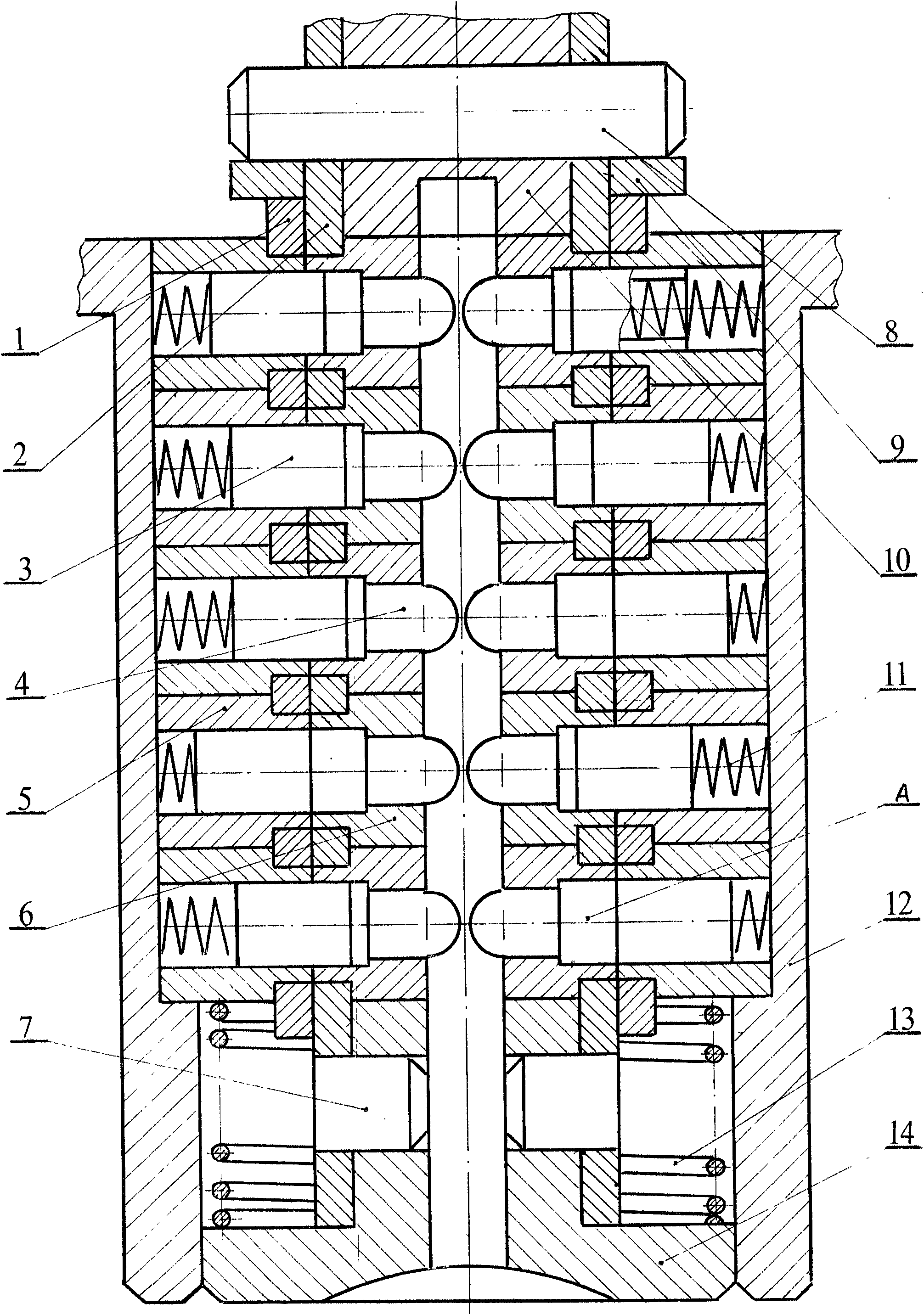
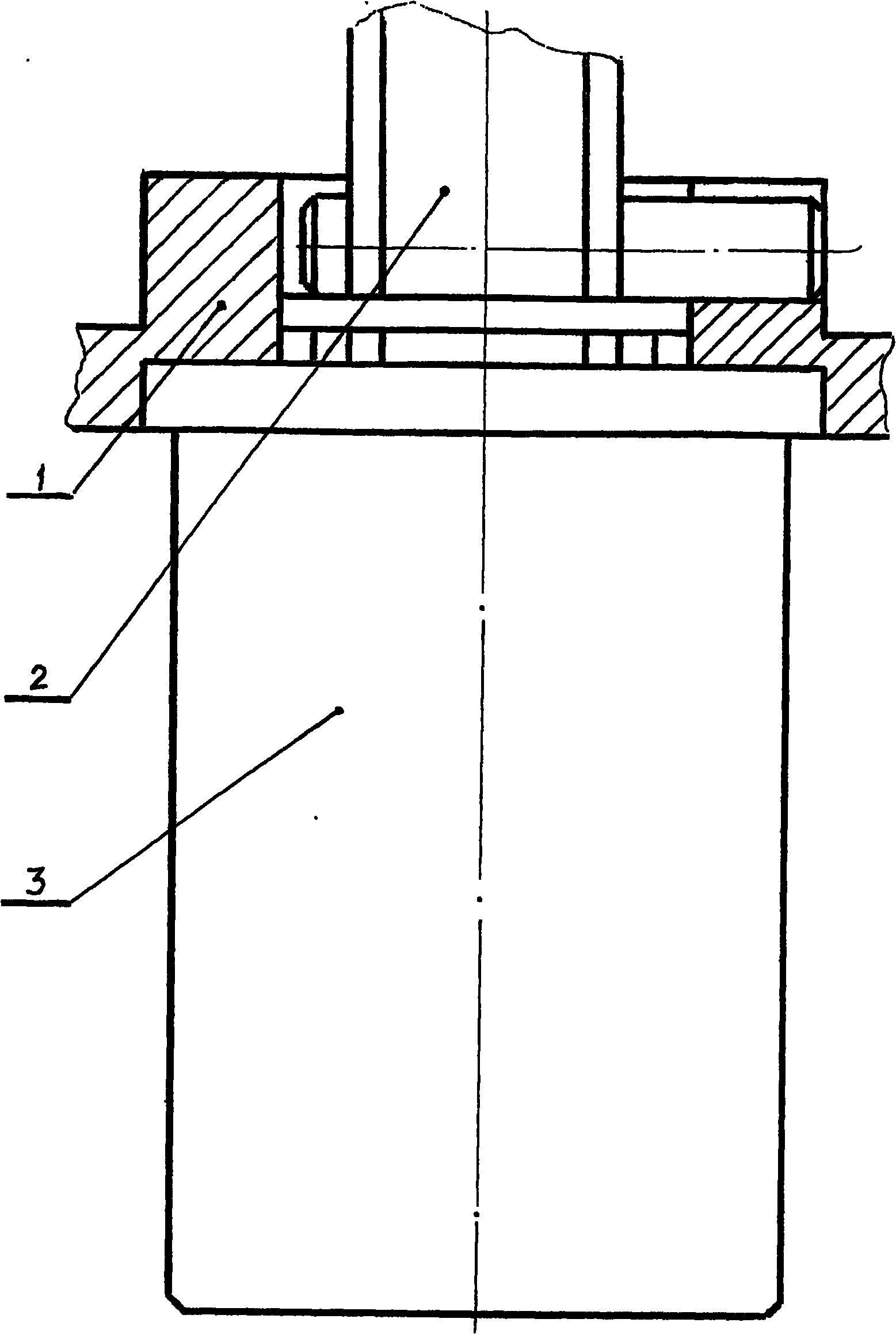
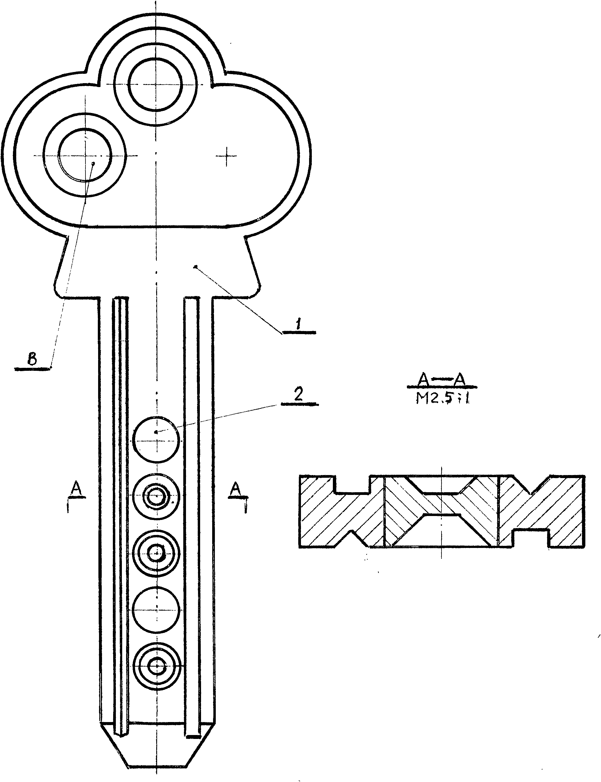
[0010] figure 1 It is an assembly drawing of the lock cylinder with a multi-level pin structure of the present invention, which is composed of a lower splint part, an upper splint part and a pin assembly. The multi-level pin structure is divided into three types of multi-level pin structure lock cylinders: 6 levels, 10 levels, and 20 levels. The arrangement of the pins is: 3 levels of pins are designed on each splint, and the splints on both sides form a 6-level pin structure lock cylinder. Design 5 gear pins on each splint, and the splints on both sides form a lock cylinder with 10 pin pin structures. A double row of pins with 5 gears is designed on each splint to form 10 pins per splint, and the splints on both sides form a lock cylinder with 20 pins. The design of the lock cylinder fully considers the processing technology of its parts. Therefore, the structure of the ...


PUM


Abstract

The invention discloses an anti-theft lock core with a multi-gear marble structure and an application thereof on an anti-theft frame lock. The lock core structure comprises an upper clamping plate 1, a lower clamping plate 2, an upper marble 3, a lower marble 4, an upper clamping plate pipe 5, a lower clamping plate pipe 6, a short shaft pin 7, a long shaft pin 8, a positioning piece 9, a cushion block 10, an upper marble pressure spring 11, an upper clamping plate jacket 12, a pushing disk pressure spring 13 and a pushing disk 14. A is a sealed marble which is a go side in a normal state. Because the invention changes the traditional lock core structure and the traditional drilling process, the coaxiality accuracy of an upper marble hole and a lower marble hole of the lock core is ensured, so that the lock core can be designed into an anti-theft lock core with a 6-gear, 10-gear or 20-gear marble structure. The lock core can be unlocked in a linear pushing mode, and in order to adapt to the requirements of the related prior art, the lock core can be also designed for unlocking in a 360 degree rotating mode. Because the current anti-theft lock can not perform an anti-theft function, the invention can enable the anti-theft lock to really perform functions of guard against theft and security.

Description

technical field [0001] The invention relates to a mechanical structure lock, in particular to an anti-theft lock cylinder with a multi-level pin structure and its application. Background technique [0002] The tumbler structure lock has been invented for more than 100 years. Because of its reliable structure and convenient opening, it has been adopted by various locks. At present, the tumbler structure locks on the market can be divided into three types according to the arrangement of the pins: one uses a flat key, and the pins are in the The outer circle of the lock cylinder is arranged in a straight line. One uses a cross key, and the marbles are arranged around the outer circle of the lock cylinder. Another kind adopts the sleeve key, and the marbles are arranged around the end face of the lock cylinder. Of these three structural locks, the flat key lock was first invented, and the pins were designed to be in three to five gears. Later, in order to prevent theft and imp...

Claims


Application Information

Patent Timeline
IPC IPC(8): E05B27/06E05B71/00E05B19/08
Inventor 刘生豹
Owner 靖江市悦达安防设备有限公司
Learn More