
Head oscillating structure of warmer

A technology of a heater and a rotating part is applied in the field of the transformation of the shaking head structure, which can solve the problems of difficult to pass 750,000 shaking shaking tests, low assembly efficiency, and short shaking head life, and achieve a simple and compact appearance, improve assembly efficiency, and save space. The effect of size

Active Publication Date: 2012-07-11
MIDEA GRP CO LTD
View PDF0 Cites 0 Cited by
  • Summary
  • Abstract
  • Description
  • Claims
  • Application Information

AI Technical Summary

Problems solved by technology

[0002] Most of the oscillating head structures of existing heaters are mainly crank-connecting rod structures, gears, and rack structures. These traditional structures have disadvantages such as complex structures, high costs, and low assembly efficiency, and these traditional oscillating head structures have short lifespan and are difficult to Passed 750,000 shaking head tests

Method used


Image

  • Head oscillating structure of warmer
  • Head oscillating structure of warmer
  • Head oscillating structure of warmer

Examples


Embodiment

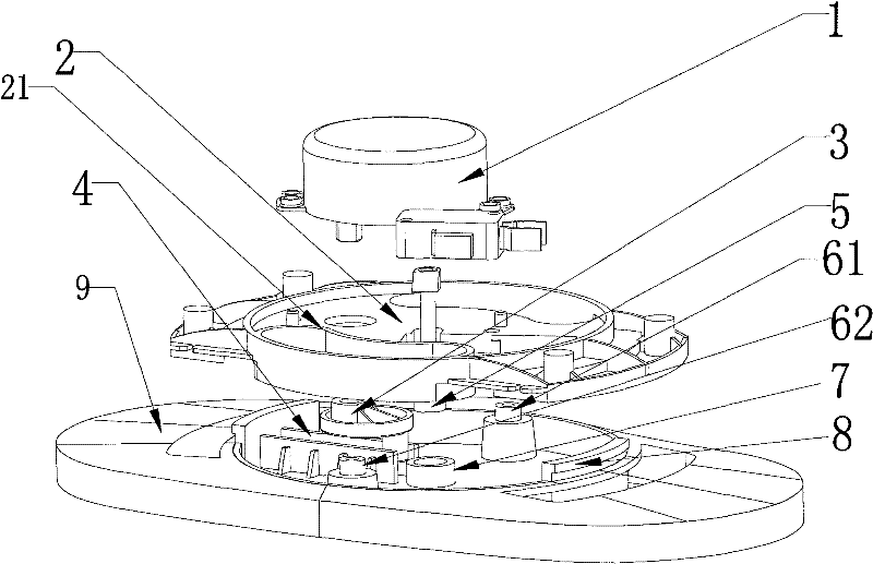
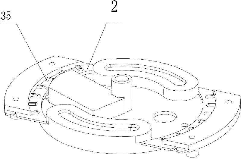
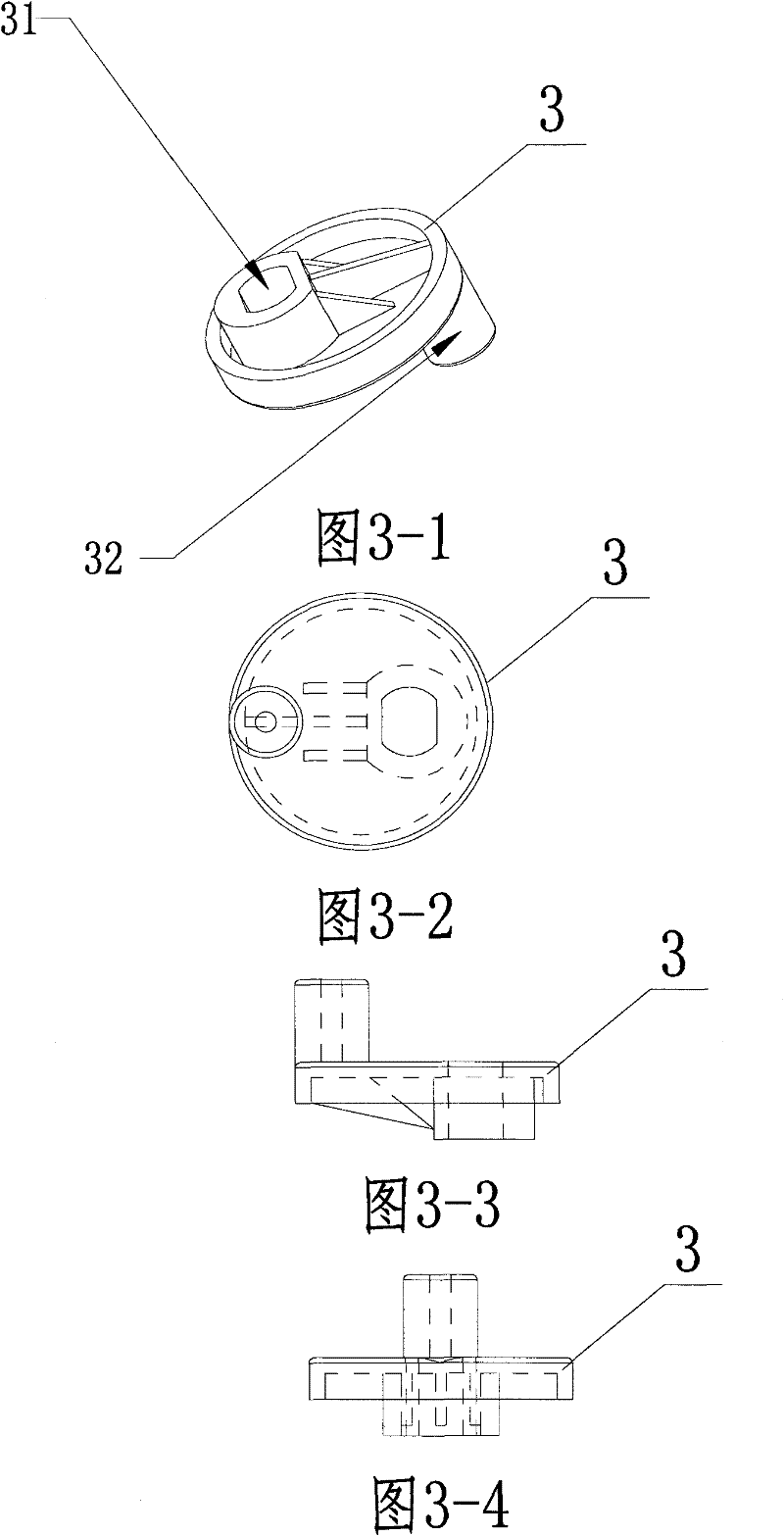
[0018] The structural schematic diagram of the present invention is as follows figure 1 , 2 As shown, including heater base 9 and rotating part 2, drive cam 3, drive motor 1, wherein drive cam 3 is placed between heater base 9 and rotating part 2, drive motor 1 is placed on top of rotating part 2, The output shaft of the driving motor 1 is inserted into the mounting hole 31 of the driving cam 3 through the rotating part 2 , and the driving shaft 32 of the driving cam 3 is placed in the slideway 4 provided on the base 9 . The sliding positioning columns 61 and 62 are installed in the rotating slideway 21 provided by the rotating part 2, and the rotating center shaft 5 provided on the rotating part 2 is sleeved on the rotating center sleeve 7 set on the base 9. The center sleeves 7 cooperate with each other to realize the rotational movement. In this embodiment, the rotation center shaft 5 and the rotation center sleeve 7 are hollow tubes, and the drive motor 1 is a synchronou...


PUM


Abstract

The invention relates to a head oscillating structure of a warmer. The head oscillating structure comprises a warmer base, a rotating part, a driving cam and a driving motor, wherein the driving cam is arranged between the warmer base and the rotating part, the driving motor is arranged at the top of the rotating part, the output shaft of the driving motor penetrates through the rotating part andis inserted into the installation hole of the driving cam, the driving shaft of the driving cam is arranged in a slide rail arranged on the base, a sliding positioning column arranged on the base is installed in the rotating slide rail arranged at the rotating part, and a rotating central shaft arranged at the rotating part is sheathed on a rotating central sleeve arranged on the base. By adopting the structure that the cam drives the rotating part to move, the space dimension of the product is reduced, the exterior smallness and exquisiteness are improved, the stability is improved and the head oscillating structure passes 750 thousand of times of head oscillation tests. Moreover, screws are not used for the fixation between the cam and the rotating part and between the rotating part andthe base slide rail, the assembling efficiency is improved and the cost is reduced.

Description

technical field [0001] The invention relates to a shaking head structure of a heater, which belongs to the transformation technology of the shaking head structure of the heater. Background technique [0002] Most of the swing structures of the existing heaters are mainly based on the crank connecting rod structure and the gear and rack structure. These traditional structures have disadvantages such as complex structure, high cost, and low assembly efficiency. Passed 750,000 shaking head tests. SUMMARY OF THE INVENTION [0003] The purpose of the present invention is to consider the above problems and provide a swing structure of a heater with simple structure, low cost, stable performance and long service life. [0004] The technical scheme of the present invention is: the shaking head structure of the heater of the present invention includes a heater base, a rotating part, a driving cam, and a driving motor, wherein the driving cam is placed between the heater base and t...

Claims


Application Information

Patent Timeline
Patent Type & Authority Patents(China)
IPC IPC(8): F24D19/00
Inventor 武文超张军聂勇杜文波
Owner MIDEA GRP CO LTD
Learn More