X-ray crystal orientation device

An orientation instrument and X-ray technology, applied in the field of X-ray detection devices, can solve problems such as unsatisfactory, reprocessing, re-submission, waste of raw materials, and long chip usage time, etc., so as to shorten the inspection period and detect Good effect, small investment effect

Inactive Publication Date: 2010-07-14
DONGDAN AOLONG RADIATIVE INSTR GRP
0 Cites 11 Cited by

AI-Extracted Technical Summary

Problems solved by technology

Sometimes it can be adjusted within the adjustable plane, and processed after adjustment, and the wafer that has been cut off by one knife has to be sent for inspection. Since the adjustment can only be based on experience, and it is a small angle, sometimes one adjustment is not satisfactory, and it needs to b...

Abstract

The invention relates to an X-ray orientation device for measuring the crystal orientation deviation of a crystal or a crystal orientation position of a crystal bar processing crystal face. The orientation device has the structure that a sample plate is respectively arranged on the bases of two sample platforms of the orientation device; one end of a support plate is connected with the sample plate, a bearing trolley capable of supporting is installed at the bottom of the other end of the support plate; a T-shaped gib capable of moving backwards and frontwards is installed in a guide rail and is fixed on the support plate; the T-shaped gib is respectively connected with a lower layer plate and a bottom plate of the two sample platforms; the upper layer plate of the right sample platform is connected with the lower layer plate by a rotation axis; the upper layer plate is provided with a trolley group, a triangular thimble is connected with the sample plate, a movable sheath is connected with the triangular thimble, a spring is connected to the movable sheath, and two columns on the left sample platform are fixed on the bottom plate. In order to achieve the purpose that the crystal bar can be processed through orientation once, a clamping device and an adhering device are additionally designed and are matched in use so that the crystal face has simple orientation of the minimum deviation angle, favorable detection effect and shortened check-submitting cycle.

Application Domain

Technology Topic

EngineeringCrystal orientation +2

Image

  • X-ray crystal orientation device
  • X-ray crystal orientation device
  • X-ray crystal orientation device

Examples

  • Experimental program(1)

Example Embodiment

[0016] The present invention will be further described below in conjunction with the drawings.
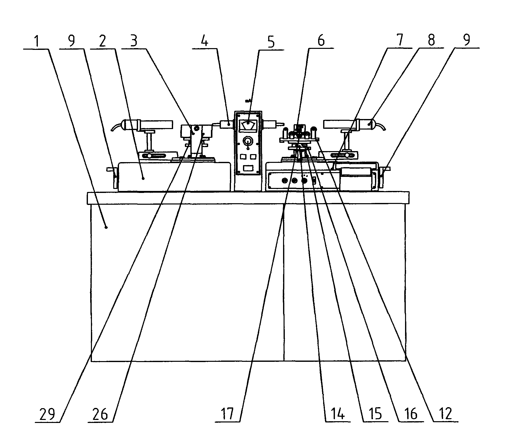
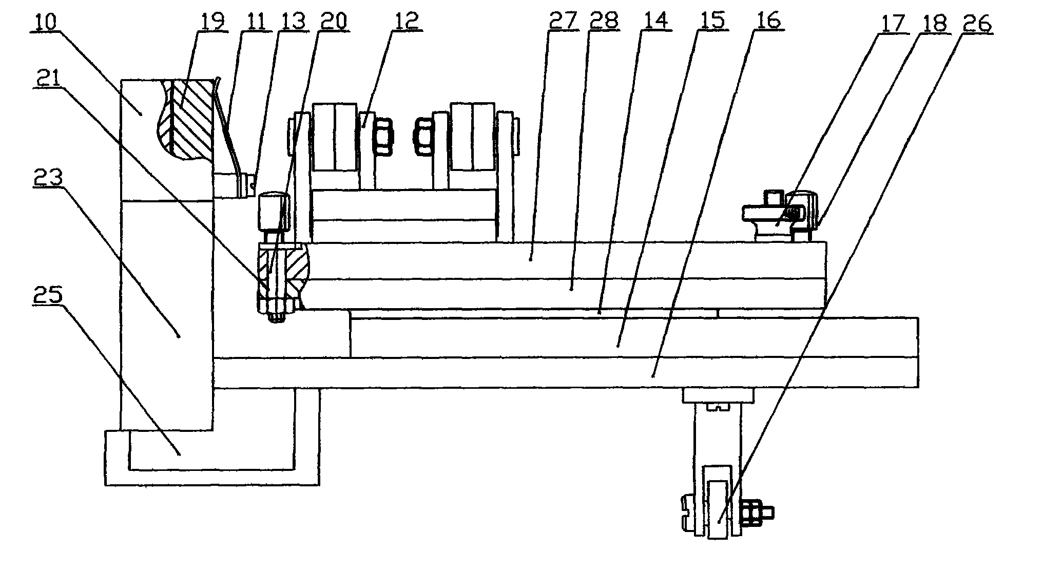
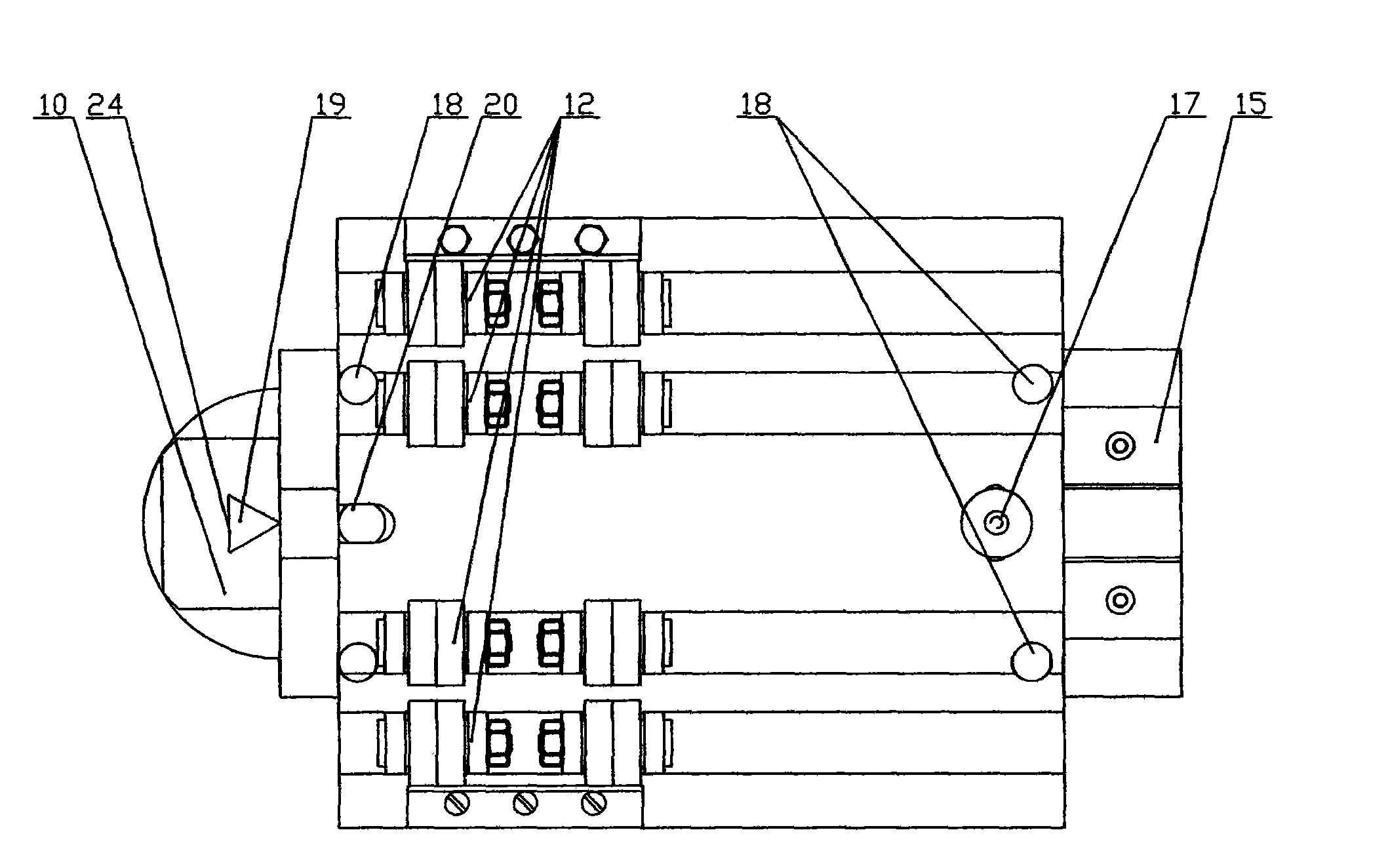
[0017] An X-ray crystal orientation instrument, such as figure 1 , figure 2 , image 3 , Figure 4 , Figure 5 As shown, it includes a table body 1 and an X-ray tube sleeve 5 set on the table body 1, two diaphragms 4, a goniometer 2 and a goniometer 7, which are set on the goniometer 2 and the goniometer 7 The handwheel 9 and the left sample stage 3 and the right sample stage 6 and the counter tube 8 installed coaxially with the goniometer. The goniometer adopts a turbo-worm structure. Rotating the handwheel 9 can make the left sample stage 3 and The right sample stage 6 rotates, and the counter tube 8 can be manually rotated coaxially with the goniometer. X-rays are emitted from the tube sleeve 5 and hit on the crystal to be inspected in the center of the sample stage through the diaphragm 4. Different crystal faces of the crystal will be diffracted at different angles and received by the counter tube 8 coaxially connected with the main axis of the goniometer. The inventive point of this utility model is to improve the design of the right sample table 6 and the left sample table 3. Its structure is as follows: the base 25 of the right sample table 6 is equipped with a sample plate 23, and one end of the support plate 16 is connected with the sample plate 23, The bottom of the other end of the pallet 16 is equipped with a bearing roller 26 that can play a supporting role. The guide rail 15 is equipped with a T-shaped insert 14 that can move forwards and backwards and is fixed on the pallet 16. The T-shaped insert 14 is connected to the lower plate 28 and the upper layer The plate 27 is connected to the lower plate 28 through the rotating shaft 20. The upper plate 27 is provided with a T-shaped groove. One end of the rotating shaft 20 is milled into a flat shape and just sinks into the T-shaped groove to limit the rotation of the rotating shaft and the upper plate 27. A hole 21 provided at the left end of the lower plate 28 passes through the rotating shaft 20. The end of the rotating shaft 20 has threads. The lower plate 28 is fixed by a nut. The upper plate 27 and the rotating shaft 20 can rotate relative to the lower plate 28. The upper plate 27 is provided with a roller set 12, the ingot itself can rotate on the roller set 12, and the upper plate 27 and the lower plate 28 can be locked by nuts 17. When detecting, first lock the upper and lower layers, and rotate the crystal rod on the sample stage to a predetermined angle of the known crystal plane. At this time, diffraction occurs, and the crystal rod itself can be rotated. When the intensity of the counter tube 8 is maximum, the crystal rod will be on the horizontal plane. The deviation is minimal. Then the crystal rod is rotated by 90°. At this time, the measured crystal plane deviation of the crystal rod is the largest. At this time, loosen the nut 17 and slightly rotate the upper plate 27 of the right sample stage 6 until the counter tube 8 receives the maximum intensity. At this time, the deviation on the horizontal plane is the smallest. Now the deviation of the inspected crystal surface of the ingot bar is the smallest relative to the entire right sample table 6. Tighten the nut 17 to lock the upper and lower layers. At this time, the physical axis of the ingot bar is relatively to the T-shaped insert 14 Angle, and the crystal orientation of the crystal rod has been adjusted to the best. In addition, the relative translation of the T-shaped insert 14 and the pallet 16 is locked by the screw 18, so that the crystal rod will remain stationary during other operations. The triangular thimble 19 is connected to the sample plate 23, and the removable sheath 10 is sleeved on the triangular thimble 19 through a triangular slot 24 in the middle, and is closely matched with the triangular thimble 19. The spring 11 is used when adjusting the machine or testing sheet samples, and is connected to the removable sheath 10 by a screw 13. When testing rod-shaped samples, the removable sheath 10 together with the spring 11 is removed from the triangular thimble 19, and the triangular thimble 19 is used to make point contact with the crystal rod, which facilitates the rotation of the crystal rod without being restricted by the removable sheath 10 The crystal face of the crystal rod to be inspected.
[0018] In order to ensure that the present invention can achieve the purpose of processing in one orientation, the clamping device and bonding device are specially designed as the supporting equipment of the present invention. The structure of the clamping device is as follows Image 6 , Figure 7 Shown. A connecting plate 43 is provided on both sides of the clamping device. The two connecting plates 43 are provided with a pair of parallel holes 42 with different heights. When the shaft 41 is inserted into the different parallel holes 42 of the connecting plate 43, it is connected with the nut 40. When connecting, the height of the nut 40 can be made different to be suitable for clamping ingots of different diameters, Image 6 The dotted line in the middle indicates the morphology of the clamped ingots of different diameters. Two holes 44 are provided in the lower part of the connecting plate 43, and the clamping device can be installed on the lower plate 28 of the right sample table 6 by screws. The screw 39 is screwed into the nut 40, and the screw 39 is rotated, and the rubber pad 45 under the screw 39 clamps the crystal rod. At this time, the crystal rod with the crystal direction adjusted on the roller set 12 and the T-shaped insert 14 on the right sample stage and the lower plate 28, the rotating shaft 20, the upper plate 27, the roller set 12 and the T insert 14 connected to the T insert 14 The clamping device installed on the lower board 28 is integrated. At this time, the screw 18 is loosened, and the above-mentioned integrated assembly is removed from the guide rail 15 and taken to the bonding device. The structure of the bonding device is as Picture 8 , Picture 9 As shown, the T-shaped insert 14 in the above-mentioned assembly is vertically downwardly inserted into the guide rail 47 of the bonding device. A graphite block guide rail 50 is installed on the base 51 of the bonding device, and the T-shaped block 53 is inserted into the guide rail 50. A graphite block 55 is installed on the top of the block 53. The screw 52 installed in the middle of the front of the T block 53 is screwed into the nut plate 54 connected to the base 51. In this way, the adjustment screw 52 can make the T block 53 The graphite block 55 is translated relative to the base 51, and a bonding guide rail 47 is installed on the vertical plate 48 connected to the base 51, so as to ensure that the vertical plate 48 is perpendicular to the base 51, and also to ensure that the bonding guide 47 is perpendicular to the graphite block 55. So as to ensure that the ingot is perpendicular to the lower surface of the graphite block 55, as a reference for the next inspection of the first processing surface of the ingot, adjust the position of the graphite block 55 to accept the ingot, and apply glue between the graphite block 55 and the ingot, and wait for the glue to dry. Remove the crystal rod and graphite block 55 to be tested. Install the T-shaped insert 14 and the lower plate 28, the rotating shaft 20, the upper plate 27, and the roller set 12 connected with the T insert 14 to the original position of the right sample table 6; Remove the lower plate 28 and use it next time the crystal rod is clamped.
[0019] Take the crystal rod and graphite block 55 to the left sample table 3 on the goniometer 2 at the other end of the orientation instrument. The base 25 of the left sample table 3 is equipped with a left sample plate 34. One end of the left support plate 33 is connected to the left sample plate. 34 is connected, the bottom of the other end of the left pallet 33 is equipped with a supporting bearing roller 26, and the left guide rail 29 is equipped with a left T-shaped insert 30 that can move forward and backward and is fixed on the left pallet 33. The left T-shaped insert The strip 30 is connected to the bottom plate 31. The bottom plate 31 is fixed with two cylinders 32 by screws. The two cylinders 32 and the left sample plate 34 form a three-point clamping ingot. Because the end face of the tested ingot is the most Benchmark, in order to prevent the crystal rod from being affected by its diameter and without losing the benchmark, three-point clamping is used. Push the crystal ingot to the center detection position of the left sample plate 34, use the bottom surface of the graphite block 55 that accepts the crystal ingot as the reference surface, and lean against the left support plate 33, then rotate the crystal ingot to find the surface of the crystal surface to be processed. Processing the reference surface, when the strength is maximum, the relative translation of the left T-shaped insert 30 and the left pallet 33 is locked by the screw 35, the line is drawn, and the processing is sent, and the entire orientation detection work is completed.

PUM

no PUM

Description & Claims & Application Information

We can also present the details of the Description, Claims and Application information to help users get a comprehensive understanding of the technical details of the patent, such as background art, summary of invention, brief description of drawings, description of embodiments, and other original content. On the other hand, users can also determine the specific scope of protection of the technology through the list of claims; as well as understand the changes in the life cycle of the technology with the presentation of the patent timeline. Login to view more.

Similar technology patents

Classification and recommendation of technical efficacy words

  • Good detection effect
  • Reduce investment

Identity authentication system based on living body detection and face verification

InactiveCN107133608AHigh-precision face recognition and liveness detectionGood detection effectDigital data authenticationSpoof detectionAuthentication systemLiving body
Owner:天津中科智能识别有限公司

Passive positioning and identification system for civil unmanned aerial vehicles

ActiveCN107678023AGood ability to detect low-altitude, slow-moving and small targetsGood detection effectRadio wave reradiation/reflectionTelemetry EquipmentLow altitude
Owner:芜湖华创光电科技有限公司

Method for extracting and separating rare earth elements

ActiveUS20100319491A1High separation factorReduce investmentRare earth metal compoundsProcess efficiency improvementRare-earth elementSolvent
Owner:SHIN ETSU CHEM CO LTD +1
Why Eureka
Try Eureka