Power-ceaseless gear transmission

A technology of gear transmission and transmission, which is applied in the direction of gear transmission, belt/chain/gear, transmission, etc., which can solve the problems of mechanical shock, incapable of carrying large load power transmission, power interruption of shifting, etc., to avoid mechanical shock Effect

Inactive Publication Date: 2012-09-05
BEIJING LONGCHUANG AUTOMOBILE SERVICE
View PDF0 Cites 10 Cited by
  • Summary
  • Abstract
  • Description
  • Claims
  • Application Information

AI Technical Summary

Problems solved by technology

[0004] The purpose of the present invention is to provide a power uninterrupted gear transmission to solve the problem that the existing transmission has shifting power interruption and mechanical impact, and cannot carry large load power transmission

Method used


Image

  • Power-ceaseless gear transmission
  • Power-ceaseless gear transmission
  • Power-ceaseless gear transmission

Examples


specific Embodiment approach 1

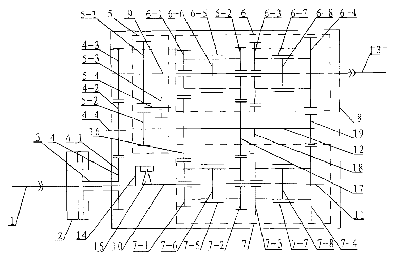
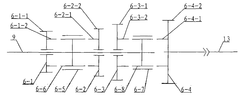
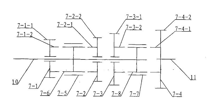
[0008] Specific implementation mode one: combine Figure 1 ~ Figure 3 Describe this embodiment, this embodiment includes input end gear mechanism 4, reverse gear mechanism 5, box body 8, drive shaft 1, clutch 2, bushing 3, main drive gear mechanism 6, secondary drive gear mechanism 7, the first Transmission shaft 9, second transmission shaft 10, second output shaft 11, third transmission shaft 12, first output shaft 13, one-way wheel input shaft 14, one-way wheel 15, first transmission gear 16, second transmission gear 17. The third transmission gear 18 and the fourth transmission gear 19, the one-way wheel input shaft 14 is located at the output end of the drive shaft 1, and the one-way wheel input shaft 14 is integrated with the drive shaft 1, and the sleeve 3 is set on the drive shaft 1, the input end of the drive shaft 1 is located outside the box body 8, and the bushing 3 is arranged on the box body wall of the box body 8 through bearings, the input end of the clutch 2 is...

specific Embodiment approach 2

[0009] Specific implementation mode two: combination figure 1 Describe this embodiment, the input end gear mechanism 4 of this embodiment is made up of input end driving gear 4-1, input end intermediate gear 4-2, input end driven gear 4-3 and input end intermediate shaft 4-4, the input end The passive gear 4-3 is fixed on the input end of the first transmission shaft 9, the input end driving gear 4-1 is fixed on the output end of the shaft sleeve 3, and the input end intermediate gear 4-2 is connected with the input end driving gear 4 at the same time. -1 meshes with the driven gear 4-3 at the input end, the intermediate gear 4-2 at the input end is fixed on the intermediate shaft 4-4 at the input end, and the intermediate shaft 4-4 at the input end is arranged on the box body wall of the box body 8 through bearings . The input end driving gear 4-1 has the same pitch circle diameter and the same number of teeth as the input end intermediate gear 4-2, and the pitch circle diam...

specific Embodiment approach 3

[0010] Specific implementation mode three: combination figure 1 Describe this embodiment, the reverse gear mechanism 5 of this embodiment is made up of reverse gear driving gear 5-1, reverse gear passive gear 5-2, reverse gear intermediate gear 5-3 and reverse gear intermediate shaft 5-4, reverse gear The driving gear 5-1 is fixed on the first transmission shaft 9, the reverse gear driven gear 5-2 is fixed on the third transmission shaft 12, and the reverse intermediate gear 5-3 is located between the reverse driving gear 5-1 and the reverse gear. At the side end face of the driven gear 5-2, the reverse intermediate gear 5-3 is fixedly mounted on the reverse intermediate shaft 5-4 through bearings, and the two ends of the reverse intermediate shaft 5-4 are respectively arranged on the ribs of the casing 8 through the bearings. board. The reverse gear intermediate gear 5-3 can mesh with the reverse gear driving gear 5-1 and the reverse gear driven gear 5-2 simultaneously, and ...


PUM


Abstract

The invention discloses a power-ceaseless gear transmission which relates to a transmission and aims at solving the problem that the conventional transmission can not bear large loads due to the interruption of gear shifting power. The power-ceaseless gear transmission comprises a clutch, a one-way wheel, a main driving gear mechanism and an assistant driving mechanism, wherein the main driving gear mechanism and the assistant driving gear mechanism have the same gear mechanisms; a first inner gear sliding sleeve on the main driving gear mechanism slides left and right and is matched with a first-gear main driving wheel and a second-gear main driving wheel which are adjacent; a second inner gear sliding sleeve on the main driving gear mechanism slides left and right and is matched with a third-gear main driving wheel and a fourth-gear main driving wheel which are adjacent; a third inner gear sliding sleeve on the assistant driving gear mechanism slides left and right and is matched with a first-gear assistant driving wheel and a second-gear assistant driving wheel which are adjacent; a fourth inner gear sliding sleeve on the assistant driving gear mechanism slides left and right and is matched with a third-gear assistant driving wheel and a fourth-gear assistant driving wheel which are adjacent; and the power transmission is realized by the clutch and the one-way wheel. The invention is suitable for various types of large and heavy type engineering machineries and transport tools.

Description

technical field [0001] The invention relates to a transmission. Background technique [0002] There are three types of transmissions: gear transmissions, chain friction continuously variable transmissions and electro-hydraulic continuously variable transmissions. The gear transmission is a staged transmission, there are breakpoints in the transmission process, and there is a phenomenon of power transmission and connection impact; the chain friction continuously variable transmission is affected by the friction coefficient of metal materials, and there is a problem that it cannot carry large loads of power transmission; the electro-hydraulic continuously variable transmission is affected. The effect of the transmission medium cannot be used to support motion out of the environment. [0003] At present, the most advanced transmission (English name DSG) on the car is produced by German Volkswagen and used on the new Audi and Magotan. Its structure is a four-axis transmission w...

Claims


Application Information

Patent Timeline
Patent Type & Authority Patents(China)
IPC IPC(8): F16H61/34F16H3/02
Inventor 马爱民马雨佳马甲男马爱国马兰蝶王海丽
Owner BEIJING LONGCHUANG AUTOMOBILE SERVICE
Why Eureka
Try Eureka