Method for controlling a field device in automation engineering

A technology for controlling automation and field equipment, which is applied in general control systems, sequence/logic controllers, program control, program control, etc., can solve problems such as the inability to guarantee 100% off-line control, and achieve the effect of reducing test work

Active Publication Date: 2010-07-21
ENDRESS HAUSER FLOWTEC AG
View PDF0 Cites 8 Cited by
  • Summary
  • Abstract
  • Description
  • Claims
  • Application Information

AI Technical Summary

Problems solved by technology

Usually, the existing equipment DTM cannot guarantee 100% off-line control

Method used


Image

  • Method for controlling a field device in automation engineering
  • Method for controlling a field device in automation engineering
  • Method for controlling a field device in automation engineering

Examples


Embodiment Construction

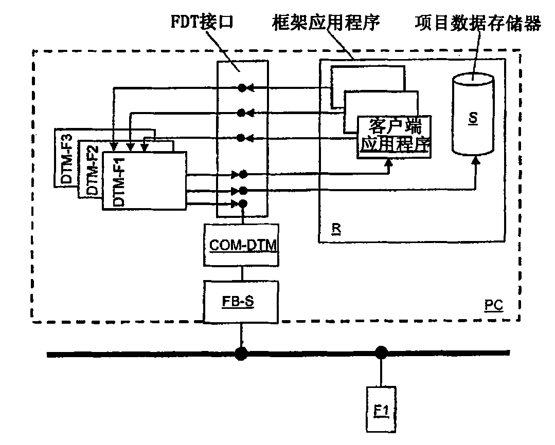
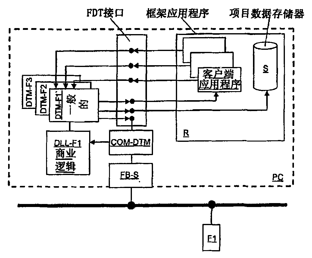
[0036] figure 1 Schematically shows the components required to control the field device F1. Usually the control takes place by means of the computer unit RE. The computer unit RE can be, for example, a personal computer PC with a Windows operating system. The computer unit RE is connected via a fieldbus interface FB-S to a fieldbus FB, to which the field device F1 is connected. Running on the computer unit RE is a framework application R (eg FieldCare from the company Endress+Hauser), which communicates via a defined interface (FDT interface) with a device DTM DTM-F1 assigned to the field device F1. There are also other device DTMs, namely DTM-F2 and DTM-F3 for field devices F2 and F3 not shown in detail.

[0037] The device DTM DTM-F1 is connected to the fieldbus interface FB-S via the communication DTM COM-DTM. In order to control the field device F1, the device DTM of the field device involved (here the device DTM DTM-F1) must be instantiated. The framework application...


PUM


Abstract

In a method for controlling a field device F1 in automation engineering with a control program which comprises a framework application and executable software components which are associated with field devices and which encapsulate the control functionalities of field devices, the software component which is associated with the field device F1 is in two parts. It comprises a basic software component and an expansion software component, wherein the basic software component DTM-F1 is used for reading and writing device parameters of the field device F1 and provides a basic graphical user interface, and wherein the expansion software component DLL-F1 is produced from the program code of the device software GS of the field device F1 and provides the control functionality of the field device F1.

Description

technical field [0001] The invention relates to a method for controlling an automation technology field device as defined in the preamble of claim 1 . Background technique [0002] In automation technology (process automation / manufacturing automation) field devices are frequently used which serve to detect and / or influence process variables. Examples of field devices in this process automation technology are level measuring instruments, mass flow measuring instruments, pressure and temperature measuring instruments, pH and redox potential measuring instruments, conductivity measuring instruments, etc., which are used as sensors to detect the corresponding process variables. That is, level, flow, pressure, temperature, pH value or conductivity value. [0003] Actuators for influencing process variables are, for example, valves controlling the flow of liquids in pipe sections or pumps changing the filling level in containers. [0004] The company manufactures and sells a l...

Claims


Application Information

Patent Timeline
Patent Type & Authority Applications(China)
IPC IPC(8): G05B19/042G05B19/05
CPCG05B2219/34262G05B19/056G05B2219/31132G05B2219/31121G05B2219/25428G05B19/0426
Inventor 马汀·勒菲弗
Owner ENDRESS HAUSER FLOWTEC AG
Why Eureka
Try Eureka