
Actuator and spring used therefor

A technology for actuators and spring arms, applied to springs, springs/shock absorbers, coil springs, etc., can solve the problems of increasing the possibility of spring protrusion and the impact of spring movement, so as to prevent collision, thin size, and improve service life Effect

Inactive Publication Date: 2010-07-21
SEIREN CO LTD
View PDF7 Cites 7 Cited by
  • Summary
  • Abstract
  • Description
  • Claims
  • Application Information

AI Technical Summary

Problems solved by technology

Specifically, when increasing the number of windings of the coiled elastic portion or reducing the winding diameter, the possibility of spring protrusion and the effect of the movement of the spring will increase

Method used


Image

  • Actuator and spring used therefor
  • Actuator and spring used therefor
  • Actuator and spring used therefor

Examples


Embodiment Construction

[0078] Reference will now be made in detail to embodiments of the invention, examples of which are illustrated in the accompanying drawings, wherein like reference numerals refer to like elements throughout. The embodiments are described below to explain the present invention by referring to the figures.

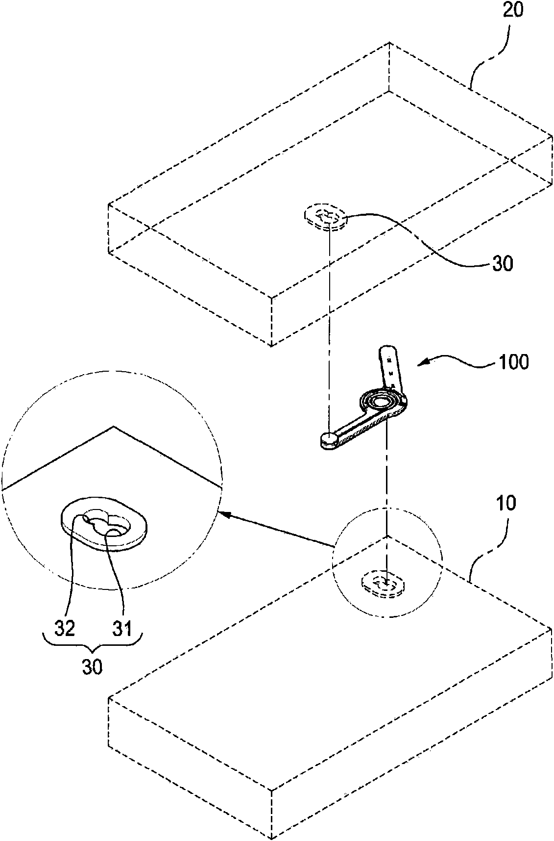
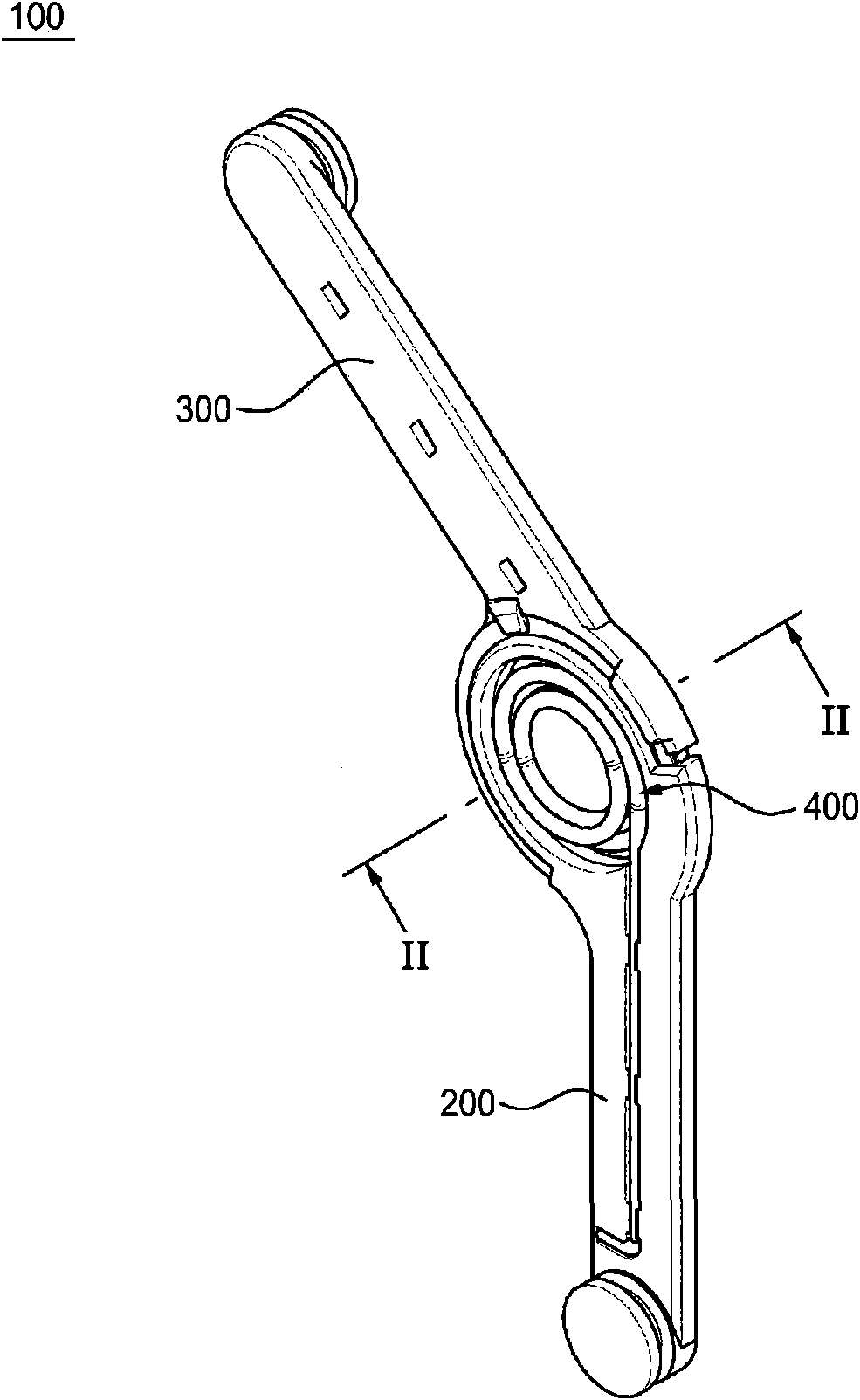
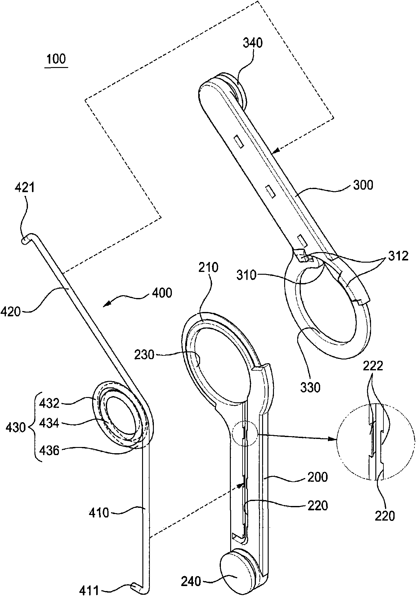
[0079] figure 1 and figure 2 is a perspective view showing the structure of an actuator according to an embodiment of the present invention, image 3 is an exploded perspective view showing the structure of the actuator according to the embodiment of the present invention.

[0080] in addition, Figure 4 is a plan view showing the structure of an actuator according to an embodiment of the present invention, Figure 5is a rear view showing the structure of an actuator according to an embodiment of the present invention, Figure 6 is along figure 2 A sectional view taken along the line II-II. Figure 7 is a perspective view showing the structure of the spring accordin...


PUM


Abstract

Disclosed are an actuator capable of preventing interference caused by torsion to thereby improve stability and reliability, and a spring used for the actuator. The actuator includes a first molding part, a second molding part being rotatably connected in an end of the first molding part, and a spring member including a first spring arm that is fixed to the first molding part and a second spring arm that is fixed to the second molding part. In this instance, the first spring and the second spring arms are integrally connected to each other.

Description

technical field [0001] The present invention relates to an actuator and a spring used for the actuator, more particularly, to an actuator capable of preventing interference caused by twisting so as to improve stability and reliability and a spring used for the actuator. the actuator spring. Background technique [0002] A slide-type mobile phone may use an actuator to provide elasticity. The actuator may provide a driving force so that the body portion and the slide portion may operate semi-automatically or automatically. A typical actuator is a torsion spring comprising a coiled elastic portion. Therefore, both ends of the torsion spring are mounted in the sliding hinge or body to provide the force for sliding. [0003] A conventional spring includes a coiled elastic portion and a wiring portion extending from the coiled elastic portion. The coiled elastic part is bent into a helical shape on the same plane. However, a disadvantage is that conventional springs cannot b...

Claims


Application Information

Patent Timeline
Patent Type & Authority Applications(China)
IPC IPC(8): H04B1/38
CPCF16F1/10F16F1/046H04M1/0237F16F2236/08
Inventor 李相昊金丙翰
Owner SEIREN CO LTD
Learn More