Electric tool

A technology for power tools and moving parts, which is applied in manufacturing tools, metal processing equipment, portable drilling rigs, etc., and can solve the problems of complex structure, high cost, and troublesome manufacturing of mechanical clutches.

CN101786178AActive Publication Date: 2010-07-28POSITEC POWER TOOLS (SUZHOU) CO LTD
4 Cites 13 Cited by

Patent Information

Authority / Receiving Office
CN · China
Patent Type
Applications(China)
Current Assignee / Owner
Publication Date
2010-07-28

Smart Images

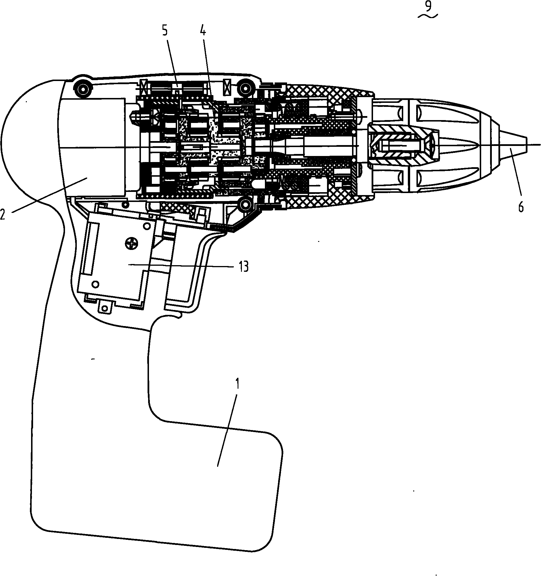
  • Figure 1
    Figure 1
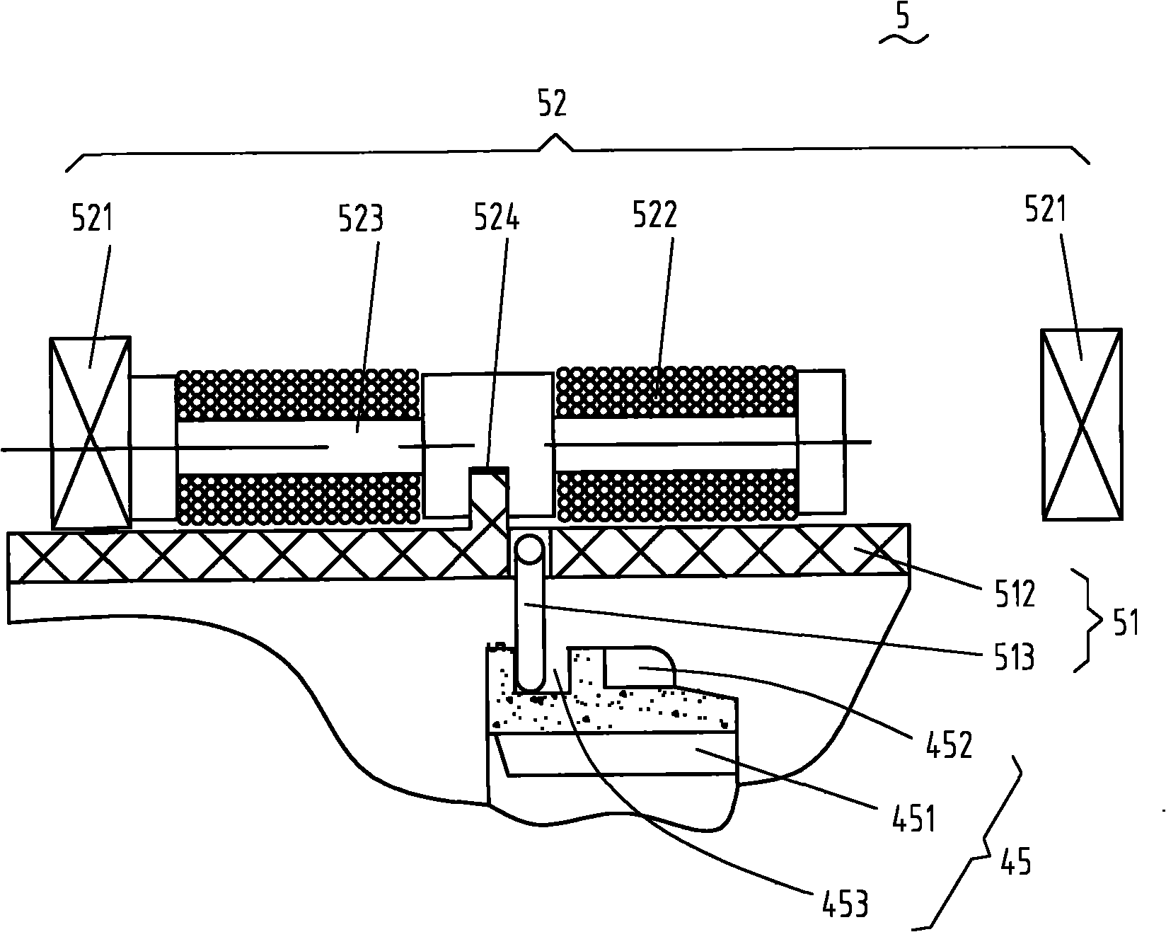
  • Figure 2
    Figure 2
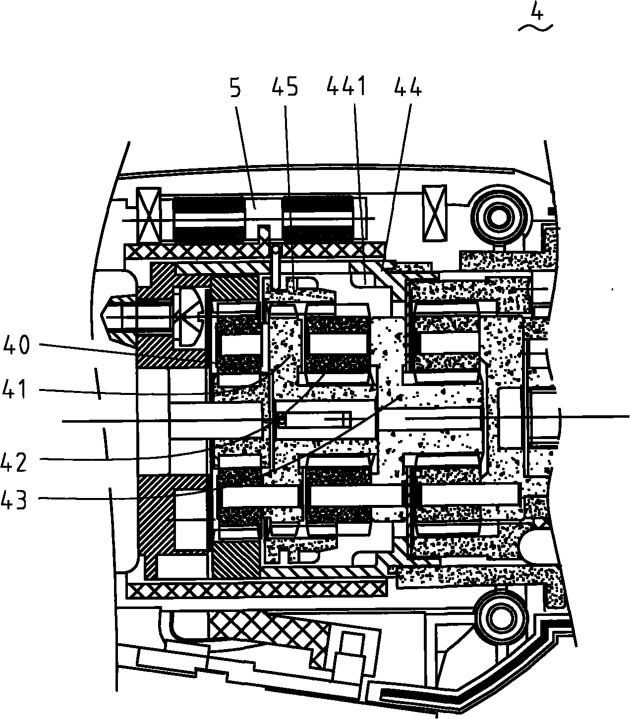
  • Figure 3
    Figure 3
Patent Text Reader

Abstract

The invention discloses an electric tool which comprises a motor, an output shaft, a gear drive mechanism, a detecting assembly and a control system, wherein the gear drive mechanism is arranged between the motor and the output shaft and has different reduction ratios; the detecting assembly is used for measuring parameters presenting the load of the output shaft; and the control system can be optionally used for controlling the tool to operate at least in one of the electronic clutch mode and the automatic gear shifting mode or the combination of the two modes. Through the structure, the automatic switching of the tool among different gears can be realized, and can prevent a work package from crossing over the position when the work package reaches a preset position.
Need to check novelty before this filing date? Find Prior Art

Description

technical field

[0001] The invention relates to an electric tool, in particular to an electric tool which can implement corresponding control according to the load condition. Background technique

[0002] An electric tool, such as an electric drill, screwdriver and hammer drill, etc., has a variable speed transmission mechanism that can output different speeds to adapt to different load torques. The variable speed transmission mechanism of electric tools usually includes a gear transmission mechanism connecting the motor and the output shaft and a control system. The control system changes the transmission ratio by changing the meshing relationship with the gear transmission mechanism, so that the output shaft outputs different speeds. In the prior art, U.S. Patent No. 6,431,289 introduces that the two ring gears in the planetary gear mechanism are arranged to move back and forth along the axial direction, and the positions of the ring gears are switched from the outside of ...

Examples

Embodiment Construction

[0065] Figure 1 to Figure 26 Disclosed is a specific implementation of the electric tool based on the automatic transmission principle of the present invention.

[0066] refer to Figure 1 to Figure 3b Shown is a schematic structural view of the first embodiment of the driving device of the electric tool control system of the present invention. An electric tool 9 includes a motor 2 , a power supply 1 for the motor, a main switch 13 for starting / stopping the motor, an output shaft 6 and a gear transmission mechanism 4 . The gear transmission mechanism 4 includes a first planetary gear set composed of a first planetary gear 40 and a first planetary carrier, a second planetary gear set composed of a second planetary gear 42 and a second planetary carrier 43, and is fixedly arranged on the tool housing The anti-rotation device 44 and the movable member 45 that can move axially. The driving device 5 is arranged on the gear transmission mechanism 4, and comprises a driving membe...