Bevel tooth differential speed reducer for mechanical main shaft of machine tool

A reducer and mechanical technology, which is applied in the direction of mechanical equipment, differential transmission, belt/chain/gear, etc., can solve the control requirements of increasing or reducing the output power and output torque of the reducer, and the output torque of the motor reducer. Torque drop, unable to meet the rated output torque and other problems

Inactive Publication Date: 2022-03-04
大连碧蓝节能环保科技有限公司
View PDF2 Cites 0 Cited by
  • Summary
  • Abstract
  • Description
  • Claims
  • Application Information

AI Technical Summary

Problems solved by technology

In order to simplify the structure of the small CNC lathe, instead of using the traditional mechanical transmission mechanism, only a reducer can be configured to increase the output torque of the small CNC lathe. The reduction ratio of the traditional reducer is fixed, and it needs to be low when processing large-sized parts. The speed is high and the torque is large. If only the frequency conversion controller is used to reduce the motor speed, the output power of the motor will decrease, resulting in a decrease in the output torque of the motor through the reducer. The existing reducer technology cannot meet the requirements of large rated output torque of CNC machine tools. And the control requirement of increasing or decreasing the output power and output torque of the reducer at the same time under the premise that the output speed of the reducer remains unchanged
[0005] In the above prior art solution, if the output speed ...

Method used


Image

  • Bevel tooth differential speed reducer for mechanical main shaft of machine tool
  • Bevel tooth differential speed reducer for mechanical main shaft of machine tool
  • Bevel tooth differential speed reducer for mechanical main shaft of machine tool

Examples


Embodiment Construction

[0048] The present invention is further described below in conjunction with accompanying drawing.

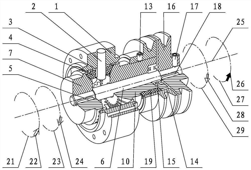
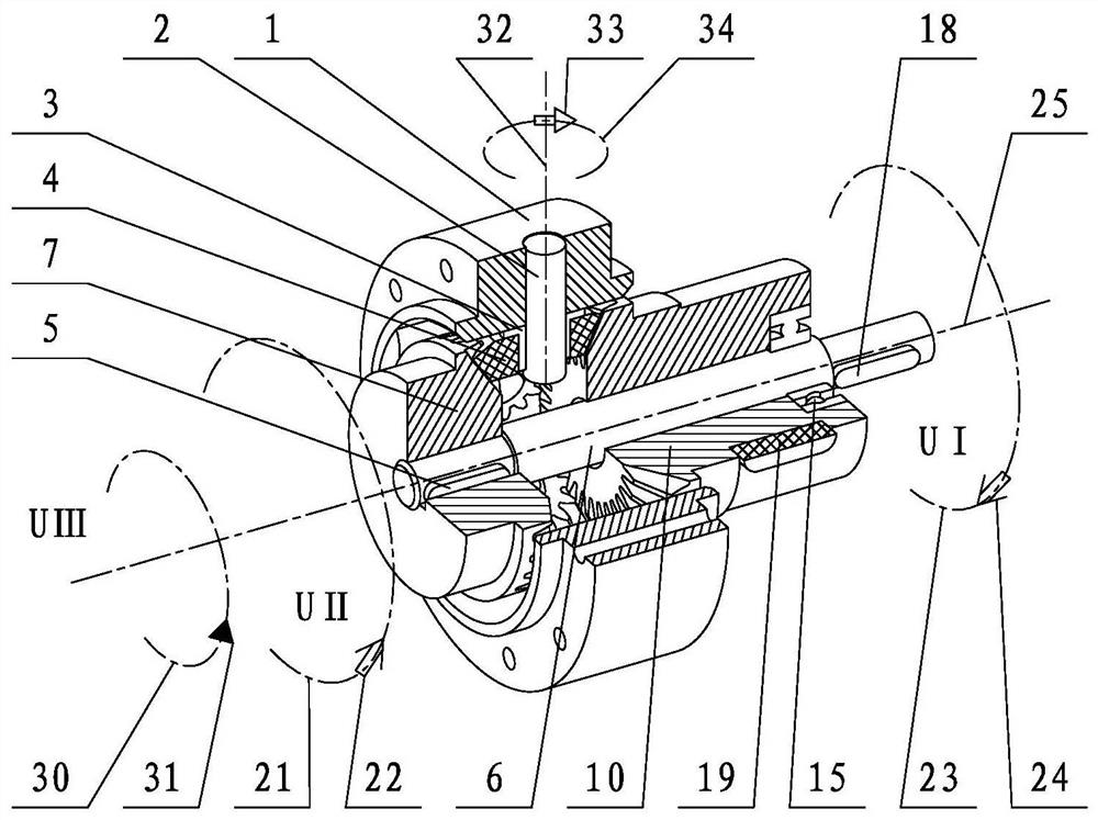
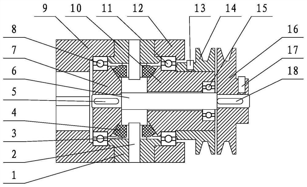
[0049] refer to Figure 1 to Figure 4 , the reducer includes an output flange part, a planet carrier part, a pressure sleeve part, and a linkage shaft part. The output flange components include an output flange 9, a bevel gear II 7 and a bearing II 8. The planet carrier components include a planet carrier 1 , a planet shaft 2 , a planet sleeve 3 and a planet bevel gear 4 . Press sleeve parts comprise press sleeve 12, bevel gear one 10, bearing one 11, bearing three 15, pulley one 14, set screw one 13, key bar three 19, set screw 20. The linkage shaft parts include linkage shaft 6, key bar one 18, key bar two 5, belt pulley two 16, set screw two 17. The output flange parts, planetary support parts, and pressure sleeve parts are arranged in sequence along the axial direction, and the output flange parts, planetary support parts, and pressure sleeve parts are connected and fixed...


PUM


Abstract

The invention relates to a speed reducer, in particular to a machine tool mechanical spindle bevel gear differential speed reducer which comprises an output flange component, a planet support component, a pressing sleeve component and a linkage shaft component. The structure size of the planetary support of the speed reducer is not limited by the radial size of the bevel gear, the bearing capacity is large, the rated output torque of the speed reducer is large under the condition that the size is not changed, and the speed reducer can change the output rotating speed and the reduction ratio. According to the speed reducer, the output power and the output torque of the speed reducer can be increased or reduced at the same time on the premise that the output rotating speed of the speed reducer is not changed, and if a first motor and a second motor arranged on the speed reducer are servo motors, the speed reducer can be accurately positioned; after accurate positioning, positioning torque is maintained to offset reverse torque transmitted by a load device, a small numerical control machine tool has the function of a numerical control rotary table capable of accurately positioning after applying the speed reducer, and the speed reducer is beneficial to design of a small numerical control compound machine tool with a simple structure.

Description

technical field [0001] The invention relates to a bevel gear differential speed reducer for a machine tool mechanical spindle, which relates to a reducer, in particular to a planetary support and an output flange located radially outside of bevel gear 1 and bevel gear 2, with a large rated output torque The machine tool mechanical spindle bevel gear differential reducer. Background technique [0002] The double bevel gear differential speed reduction mechanism of application publication number CN109854681A is a double bevel gear differential speed reduction mechanism that adopts two motors to respectively drive the speed difference between the first double bevel gear and the second double bevel gear to obtain a low speed output. Application publication number CN109736047A relates to a method for controlling a double bevel gear differential speed reduction system of a washing machine, which is a method in which a double bevel gear differential speed reduction mechanism is app...

Claims


Application Information

Patent Timeline
IPC IPC(8): F16H48/08F16H48/40F16H48/38F16H57/023F16H57/08
CPCF16H48/08F16H48/40F16H48/38F16H57/023F16H57/082
Inventor 赵晓东
Owner 大连碧蓝节能环保科技有限公司
Why Eureka
Try Eureka