Bearingless permanent magnet speed regulation system

A permanent magnet speed regulation and bearingless technology, which is applied in the direction of permanent magnet clutch/brake, casing/cover/support, control of mechanical energy, etc., can solve the problem of high maintenance cost of permanent magnet speed governor, large amount of renovation work, Long time and other problems, to achieve the effect of being suitable for popularization, reducing the amount and cost of renovation projects, and low cost

Pending Publication Date: 2021-08-10
芜湖磁轮传动技术有限公司
View PDF0 Cites 0 Cited by
  • Summary
  • Abstract
  • Description
  • Claims
  • Application Information

AI Technical Summary

Problems solved by technology

[0003] The purpose of the present invention is to solve the problems of existing permanent magnet governors such as high maintenance cost, large renovation project and long time, and provide a permanent magnet governor with simple structure, convenient maintenance and convenient renovation. speed system

Method used


Image

  • Bearingless permanent magnet speed regulation system
  • Bearingless permanent magnet speed regulation system
  • Bearingless permanent magnet speed regulation system

Examples


Embodiment Construction

[0017] The present invention will be further described below in conjunction with the accompanying drawings and embodiments.

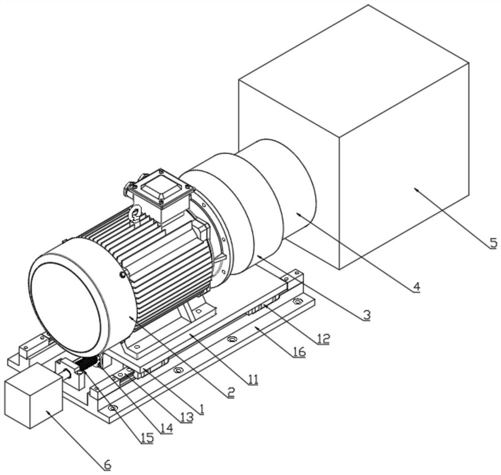
[0018] Such as Figure 1 to Figure 3 As shown, a bearingless permanent magnet speed regulating system includes a mobile base (1), a motor (2), a cylindrical conductor rotor (3) and a cylindrical permanent magnet rotor (4).

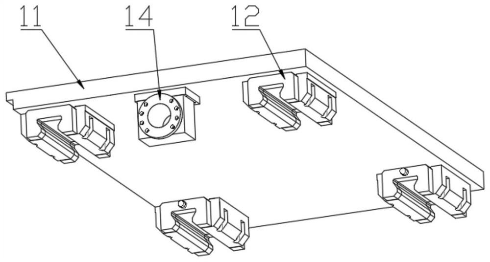
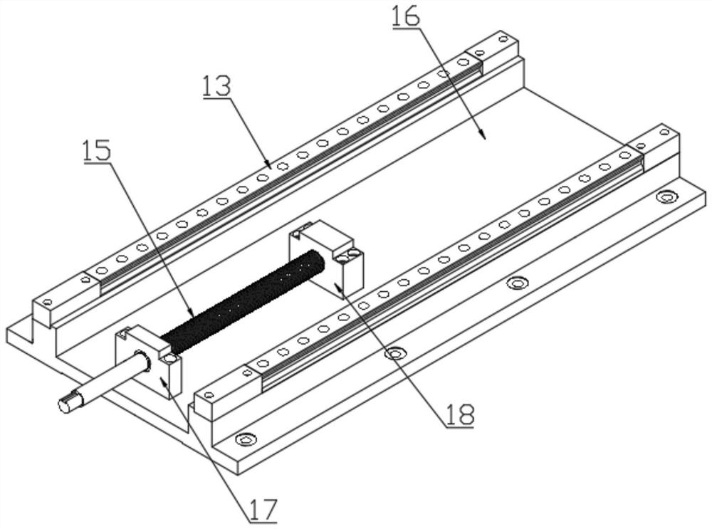
[0019] The mobile base (1) also includes an upper base plate (11), a slide block (12), a guide rail (13), a leading screw nut (14), a leading screw (15), and a lower base plate (16). The slide block (12) and the lead screw nut (14) are arranged on the lower end surface of the upper bottom plate (11), and the motor (2) is arranged on the upper end surface of the upper bottom plate (11). Guide rails (13) and leading screw (15) are arranged on the upper end surface of lower bottom plate (16), and guide rails (13) are no less than 2 pieces. The mobile base (1) also includes a support seat A (17) and a support seat B (18), and the supp...


PUM


Abstract

The invention discloses a bearingless permanent magnet speed regulation system, which comprises a movable base, a motor, a barrel-type conductor rotor and a barrel-type permanent magnet rotor, the movable base further comprises an upper bottom plate, a sliding block, a guide rail, a lead screw nut, a lead screw and a lower bottom plate; the sliding block and the lead screw nut are arranged on the lower end face of the upper bottom plate, and motor is arranged on the upper end face of the upper bottom plate; the guide rail and the lead screw are arranged on the upper end face of the lower bottom plate and are parallel to a shaft of the motor. the sliding block is matched with the guide rail, and the lead screw nut is matched with the lead screw; the cylindrical conductor rotor is arranged on a shaft of the motor; the cylindrical permanent magnet rotor and the cylindrical conductor rotor are concentrically sleeved and are separated by an air gap; the cylindrical permanent magnet rotor is arranged on a shaft of a load; the lead screw is rotated to drive the lead screw nut to move, the lead screw nut drives the motor to move, and finally the cylindrical conductor rotor is driven to move, so that the meshing area of the cylindrical conductor rotor and the cylindrical permanent magnet rotor is changed, and the load rotating speed is adjusted. The system is simple in structure, convenient to transform, low in cost and suitable for popularization and application.

Description

technical field [0001] The invention relates to the technical field of permanent magnet speed regulation, in particular to a bearingless permanent magnet speed regulation system. Background technique [0002] The permanent magnet governor is a device that uses magnetic force to achieve power transmission and speed regulation. It has the characteristics of simple structure, high reliability, and strong environmental adaptability. The permanent magnet governor adjusts the magnetic field coupling area between the conductor rotor and the permanent magnet rotor through the adjustment mechanism, thereby changing the transmitted torque and speed. At present, there are two main problems in the use of permanent magnet governors. One is that the permanent magnet governor contains bearings, which need to be maintained and replaced regularly, which increases the cost of the permanent magnet governor. The second is the permanent magnet governor. The inverter requires installation space....

Claims


Application Information

Patent Timeline
Patent Type & Authority Applications(China)
IPC IPC(8): H02K49/10H02K5/26H02K5/00H02K7/06
CPCH02K5/00H02K5/26H02K7/06H02K49/106
Inventor 陈宝寿王向东
Owner 芜湖磁轮传动技术有限公司
Why Eureka
Try Eureka