Economical milling machine bevel gear differential speed reducer

A reducer, economical technology, applied in belt/chain/gear, transmission parts, mechanical equipment, etc., can solve problems such as low torque output, affecting machining accuracy, and the inability of motorized spindles to meet technical requirements

Inactive Publication Date: 2022-02-25
大连碧蓝节能环保科技有限公司
View PDF2 Cites 0 Cited by
  • Summary
  • Abstract
  • Description
  • Claims
  • Application Information

AI Technical Summary

Problems solved by technology

The DC motor works in the constant torque mode below the rated power. The input voltage of the DC motor is proportional to the output speed and output power. When the DC voltage regulator module adjusts the input voltage of the DC motor, the output speed and output power of the DC motor decrease. If the output speed of the economical milling machine is 50r/min in the low gear of the gear transmission mechanism, the output speed of the DC motor is 200r/min, and the output power of the DC motor is only 22W. The output power is only 4.4% of the rated power, which cannot meet the cutting torque required when the economical milling machine uses a large-diameter tool or processes parts with high hardness, thus limiting the application range of the economical milling machine
[0005] The axial movement of the X-axis, Y-axis and Z-axis of the economical CNC milling machine adopts the servo motor to drive the ball screw, and the rotation of the Z-axis adopts the stepless speed change system to drive the motor, including the frequency conversion stepless speed change system to drive the asynchronous motor or synchronous motor. And the DC voltage regulation module drives the DC motor, and the technical solution of the DC voltage regulation module driving the DC motor has the lowest cost. No matter which solution is used, the motor will wor...

Method used


Image

  • Economical milling machine bevel gear differential speed reducer
  • Economical milling machine bevel gear differential speed reducer
  • Economical milling machine bevel gear differential speed reducer

Examples


Embodiment Construction

[0054] The present invention is further described below in conjunction with accompanying drawing.

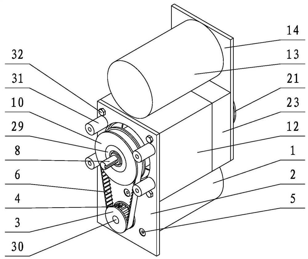
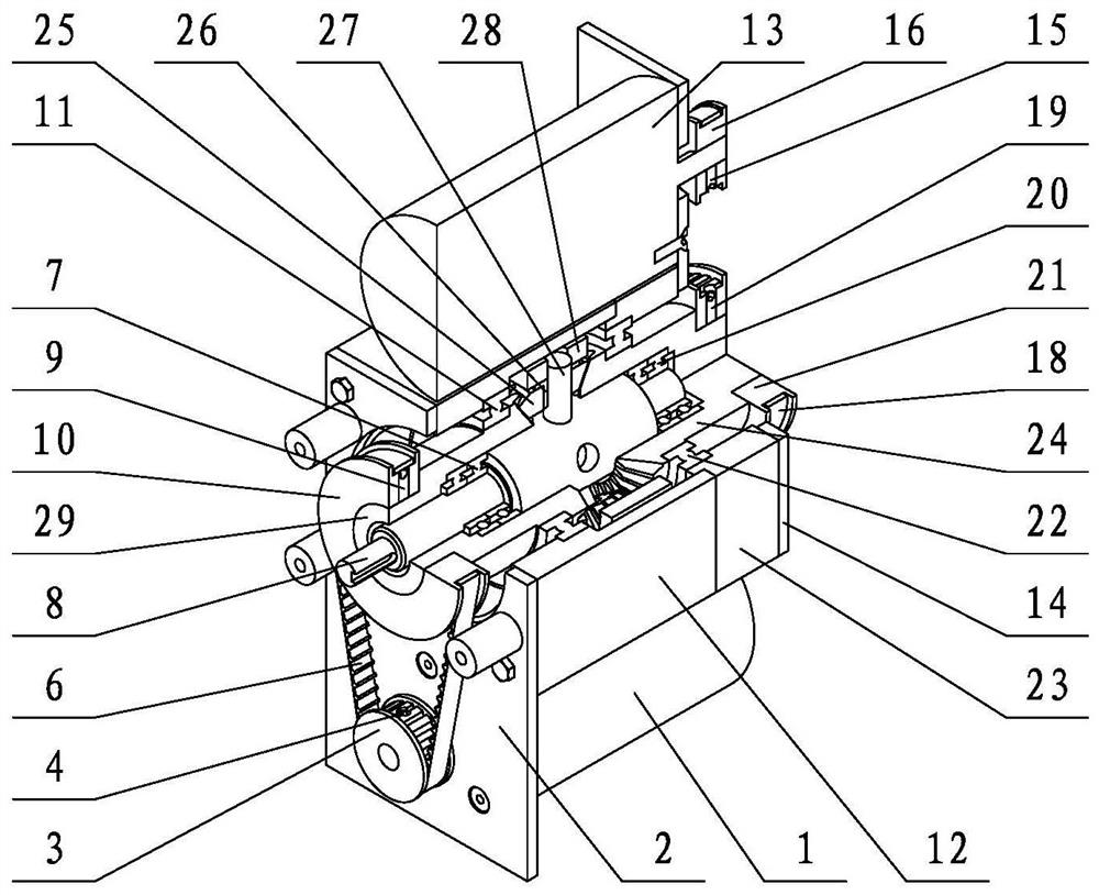
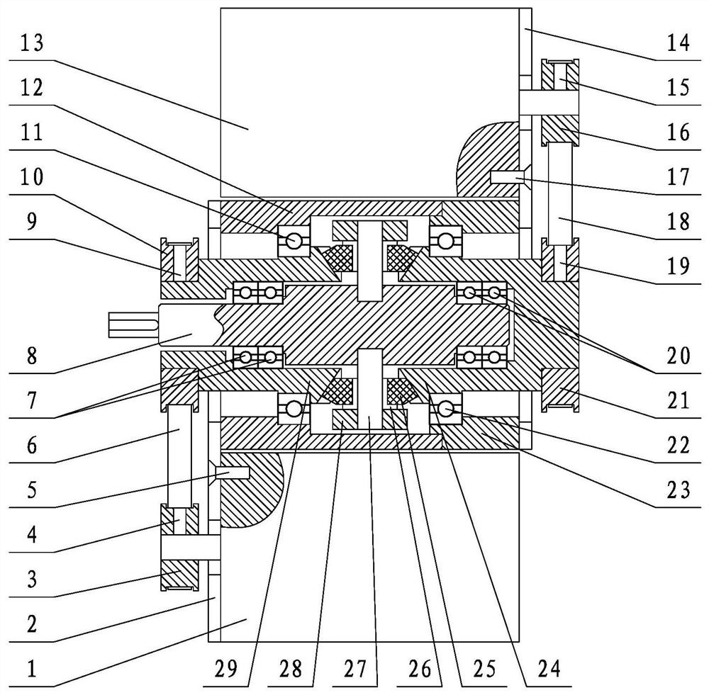
[0055] refer to Figure 1 to Figure 3 , Figure 13 , Figures 20 to 23 , The speed reducer includes a shell part one, a shell part two, a planet carrier part, a motor part one, and a motor part two. Shell component one includes a shell one 23 , a bearing one 22 , and a bevel gear one 24 . The second shell part includes a second shell 12 , a second bearing 11 , and a second bevel gear 29 . The planet carrier parts include planet carrier 28, planet shaft 27, planet bushing 26, planet bevel gear 25, output shaft 8, bearing three 20, bearing four 7. Motor part one includes motor one 13, fixing plate one 14, motor fixing screw one 17, fixing bolt one 69, motor pulley one 16, set screw one 15, belt one 18, input pulley one 21, set screw three 19. Motor part 2 includes motor 2 1, fixing plate 2, motor fixing screw 2 5, fixing bolt 2 32, motor pulley 2 3, set screw 2 4, belt 2 6, ...


PUM


Abstract

The invention relates to a speed reducer, in particular to an economical milling machine bevel gear differential speed reducer which comprises a first shell component, a second shell component, a planet support component, a first motor component and a second motor component. When the speed reducer operates, the rotating speed of the second motor is maintained to be equal to the reference rotating speed, the output rotating speed of the speed reducer is changed by changing the rotating speed of the first motor, and the output power of an output shaft of the speed reducer during low-rotating-speed operation is larger than that during high-rotating-speed operation. According to the technical characteristic that the torque required by a milling machine is large when a large-diameter cutter or a part with high machining hardness is adopted, the speed reducer can achieve the purpose that the rotating direction of the output shaft of the speed reducer is changed on the premise that the first motor and the second motor are not shut down, if the motor I and the motor II adopt closed-loop control, the speed reducer can meet the technical requirements that the Z shaft of the milling machine needs to change the rotating direction in a short time and is accurately controlled during tapping.

Description

technical field [0001] The present invention is an economical bevel gear differential reducer for milling machines, which relates to a reducer, in particular to a reducer that does not include double bevel gears, the planetary carrier is located on the radially outer side of bevel gear 1 and bevel gear 2, and is located on the casing part The economical milling machine bevel gear differential reducer with simple structure and large rated output torque is driven by belts at both ends of the axial direction. Background technique [0002] The double bevel gear differential speed reduction mechanism of application publication number CN109854681A is a double bevel gear differential speed reduction mechanism that adopts two motors to respectively drive the speed difference between the first double bevel gear and the second double bevel gear to obtain a low speed output. Application publication number CN109736047A relates to a method for controlling a double bevel gear differential...

Claims


Application Information

Patent Timeline
IPC IPC(8): F16H37/02F16H57/023F16H57/08
CPCF16H37/02F16H57/023F16H57/082F16H57/08
Inventor 赵晓东
Owner 大连碧蓝节能环保科技有限公司
Why Eureka
Try Eureka