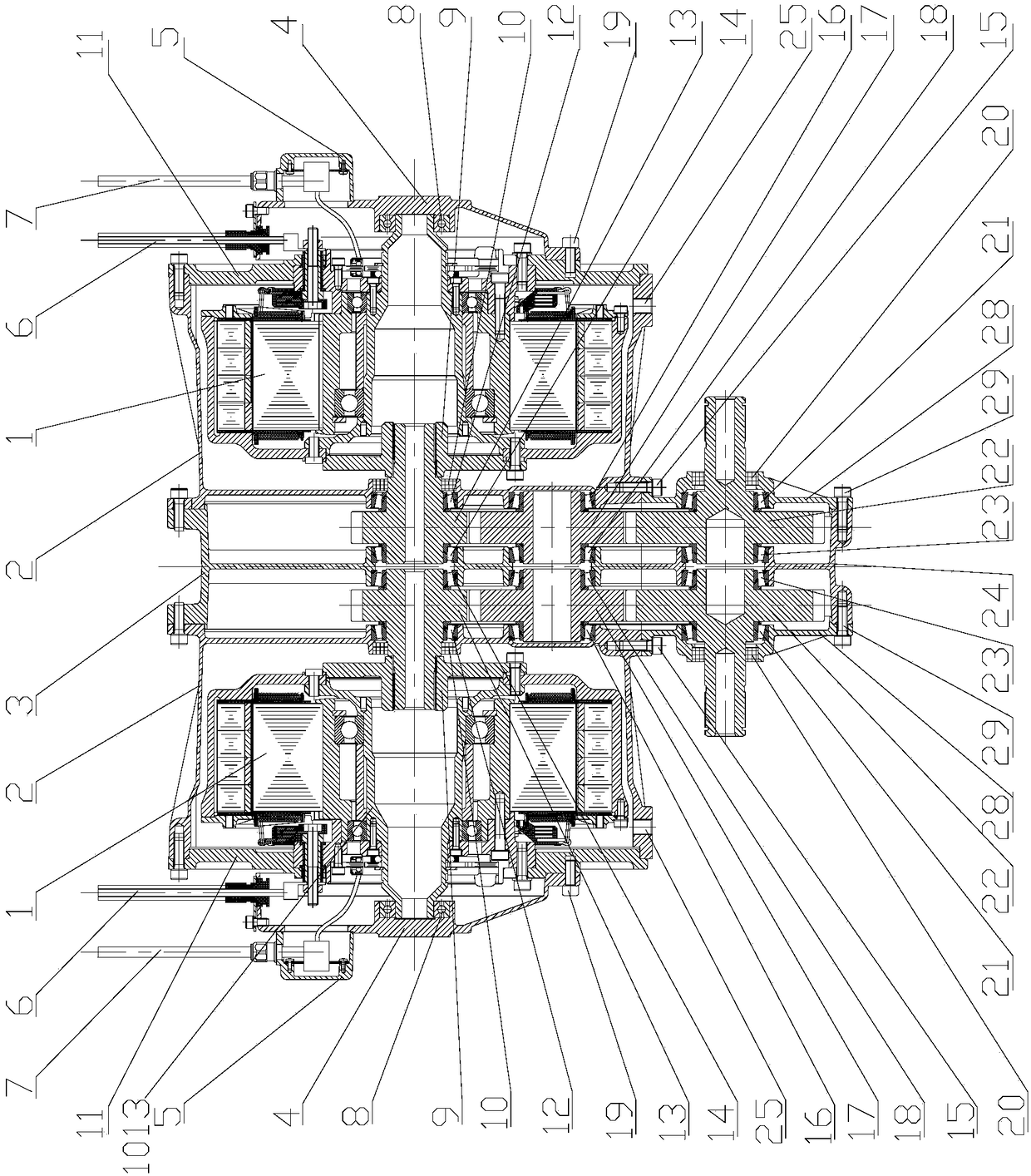
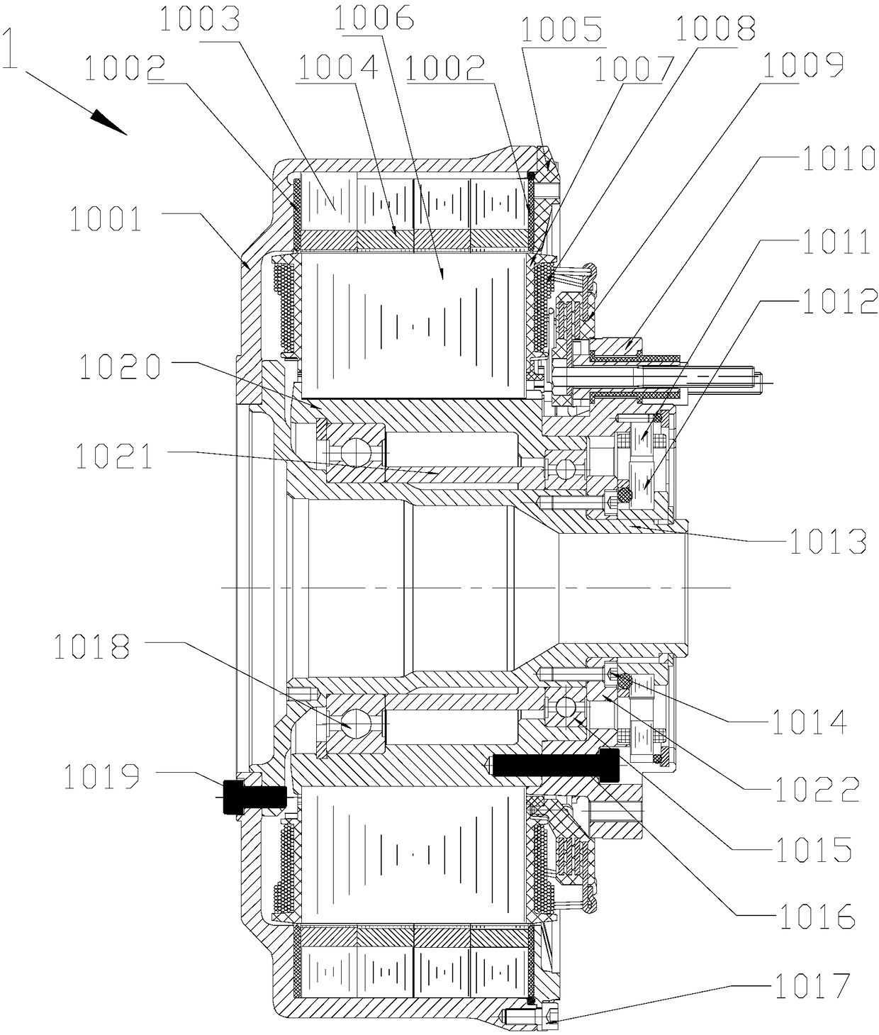
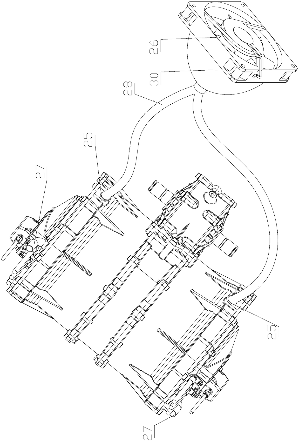
Electric power device

A technology of electric power and power output shaft, applied in the direction of electric power devices, power devices, electromechanical devices, etc., can solve the problems of low maximum speed, poor heat dissipation effect, large space, etc., to reduce the cost of use, easy to disassemble and maintain , good waterproof effect

Inactive Publication Date: 2018-06-05
SHENZHEN INST OF ADVANCED TECH
View PDF6 Cites 0 Cited by
  • Summary
  • Abstract
  • Description
  • Claims
  • Application Information

AI Technical Summary

Problems solved by technology

[0004] Hub motor drive technology has been studied by major motor and automobile manufacturers for decades, but it has not yet been put into the market in large quantities, which shows that it still has many shortcomings that have not been resolved.
At present, there are still many problems in the practical application of hub motors, such as: the maximum speed of hub motors is low, waterproof, dustproof, heat dissipation and other issues have not been effectively resolved
[0006] 1. Although the hub motor has a large torque, the maximum speed is relatively low. The maximum speed of the existing hub motor is generally only 1500-2000rpm / min. Such a speed, as a direct drive motor, cannot reach the speed of the vehicle after loading in many cases. required top speed
If each hub motor is equipped with a gearbox, it will greatly increase the complexity of the entire hub motor drive system, reduce the reliability of the entire system, and require a lot of space to add a gearbox, which will also greatly increase the production cost
[0007] 2. Due to the structural characteristics of the existing hub motor, it is difficult to achieve reliable sealing. At present, the problems of waterproof and dustproof have not been effectively solved. In the actual use process, it is easy to be damaged by water or foreign objects. Cause damage to the motor, seriously affecting the reliability and service life of the motor
Moreover, the shell of the hub motor is rotating, so it is difficult to do a water cooling system on the motor, and the heat generated by the motor can only be taken away by natural wind, and the heat dissipation effect is not good.

Method used


Image

  • Electric power device
  • Electric power device
  • Electric power device

Examples


Embodiment Construction

[0029] In order to make the object, technical solution and advantages of the present invention clearer, the present invention will be further described in detail below in conjunction with the accompanying drawings and embodiments. It should be understood that the specific embodiments described here are only used to explain the present invention, not to limit the present invention.

[0030] It should be noted that when an element is referred to as being “fixed on” or “disposed on” another element, it may be directly on the other element or there may be an intervening element at the same time. When an element is referred to as being "connected to" another element, it can be directly connected to the other element or intervening elements may also be present.

[0031] It should also be noted that the orientation terms such as left, right, up, and down in the embodiments of the present invention are only relative concepts or refer to the normal use state of the product, and should ...


PUM


Abstract

The invention is suitable for the technical field of power devices, and discloses an electric power device. The electric power device comprises a protection shell and at least two hub motors arrangedin the protection shell. Motor shafts of the hub motors are coaxial. A speed changing part is arranged in the protection shell, and comprises at least two independent transmission assemblies connectedwith the motor shafts respectively. According to the electric power device, the hub motors and the speed changing part are integrated in the protection shell, the dustproof and waterproof effect is good; the transmission rate is changed through the speed changing part, the aim of changing the output rotating speed is achieved, and therefore the output rotating speed of the hub motors can be increased, and the problems that an existing hub motor is low in highest rotating speed, poor in cooling performance and poor in waterproof and dustproof effect are solved; the electric power device is excellent in universality and simple in structure, enhances the reliability of a whole power system, and can be suitable for the technical fields of new energy vehicles and motors.

Description

technical field [0001] The invention belongs to the technical field of power devices, and in particular relates to an electric power device. Background technique [0002] With the increasingly serious energy shortage and air pollution, governments of various countries are vigorously developing energy-saving and environmentally friendly new energy vehicles. The business of new energy vehicles has developed rapidly. Especially in the past few years, in order to encourage the development of new energy vehicles, my country has successively introduced a number of support measures. These policies not only played a positive role in the research and development of new energy vehicle technology, but also played a role in the industrialization of new energy vehicles in my country. No small push. Under such a good policy environment and market expectations, my country's current new energy vehicle industry has developed rapidly, which has also led to a new energy vehicle industry syste...

Claims


Application Information

Patent Timeline
IPC IPC(8): B60K7/00B60K17/08B60K1/00H02K7/116
CPCB60K7/0007B60K1/00B60K17/08B60K2001/006H02K7/116
Inventor 刘小青潘仲鸣李程宇贾慧波
Owner SHENZHEN INST OF ADVANCED TECH
Why Eureka
Try Eureka