
Structure of mounting cowl top cover

A technology of cowl upper cover and installation structure, which is applied in the direction of upper structure, upper structure sub-assembly, transportation and packaging, etc., which can solve the deformation of the clamping part or fitting groove, reduce the quality of the vehicle, and the front wall upper cover To avoid excessive load, prevent falling, and restrain one-time shrinkage

Active Publication Date: 2010-07-28
NIHON PLAST CO LTD
View PDF1 Cites 23 Cited by
  • Summary
  • Abstract
  • Description
  • Claims
  • Application Information

AI Technical Summary

Problems solved by technology

[0005] However, with regard to the mounting structure of the cowl top in the prior art as described above, when the cowl top is integrally molded with synthetic resin, due to one-time shrinkage during molding, the entire length in the vehicle width direction On the other hand, extended clips or fitting grooves tend to be distorted, and when the volume shrinks or expands due to temperature changes, or when a single product is stored or transported under a load caused by its own weight, these clips or Fitting grooves are also prone to deformation
[0006] In this way, if the rear end of the cowl top provided at the lower end of the front windshield is deformed, it does not match the curvature of the front windshield, and the difference in curvature causes the front cowl top to deform. If there is a gap between the front windshield and the quality of the vehicle, or if you insist on installing it with the gap, there is a risk that the cowl top will receive an excessive load

Method used


Image

  • Structure of mounting cowl top cover
  • Structure of mounting cowl top cover
  • Structure of mounting cowl top cover

Examples


Embodiment Construction

[0076] Embodiments of the present invention will be described below based on the drawings.

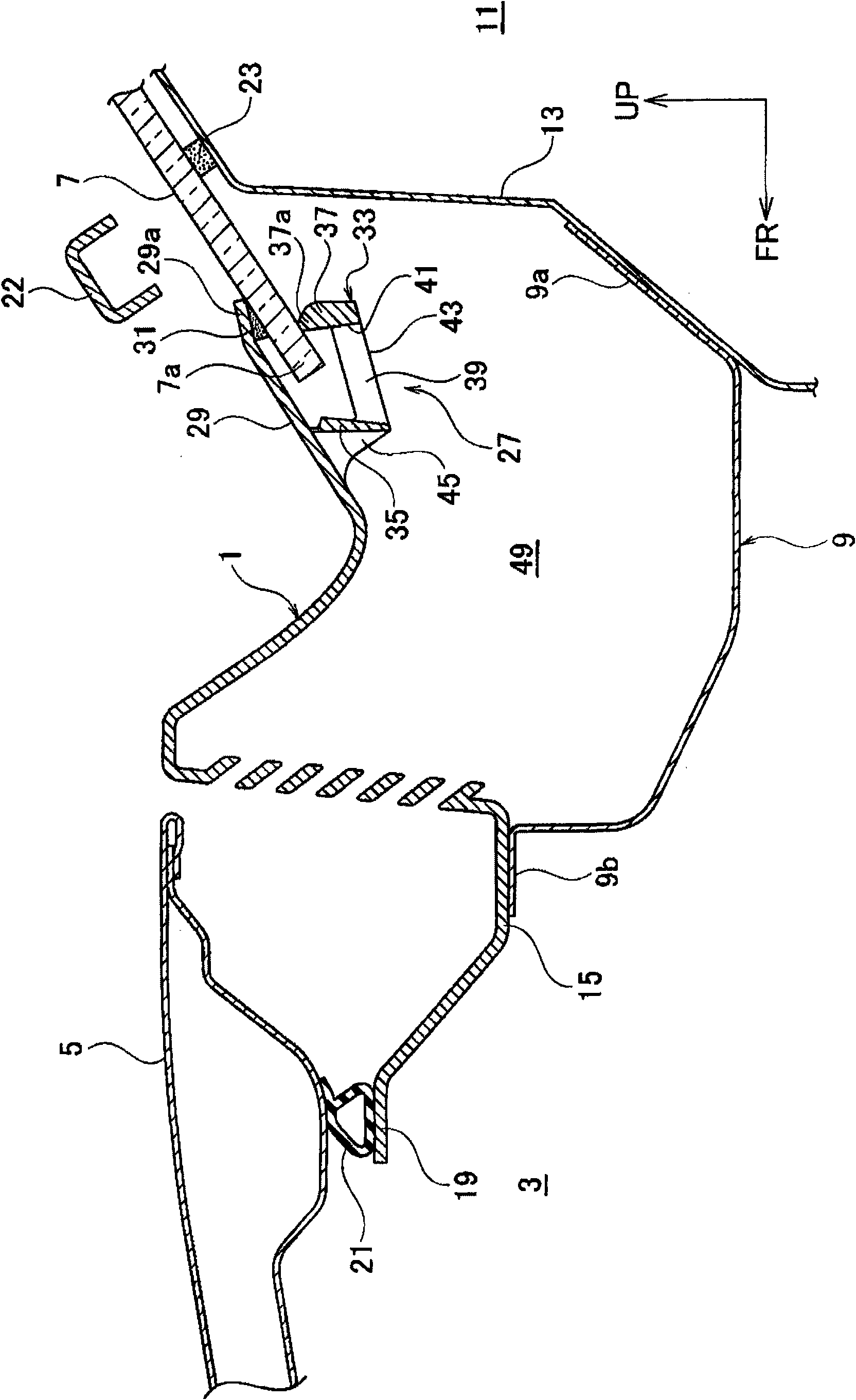
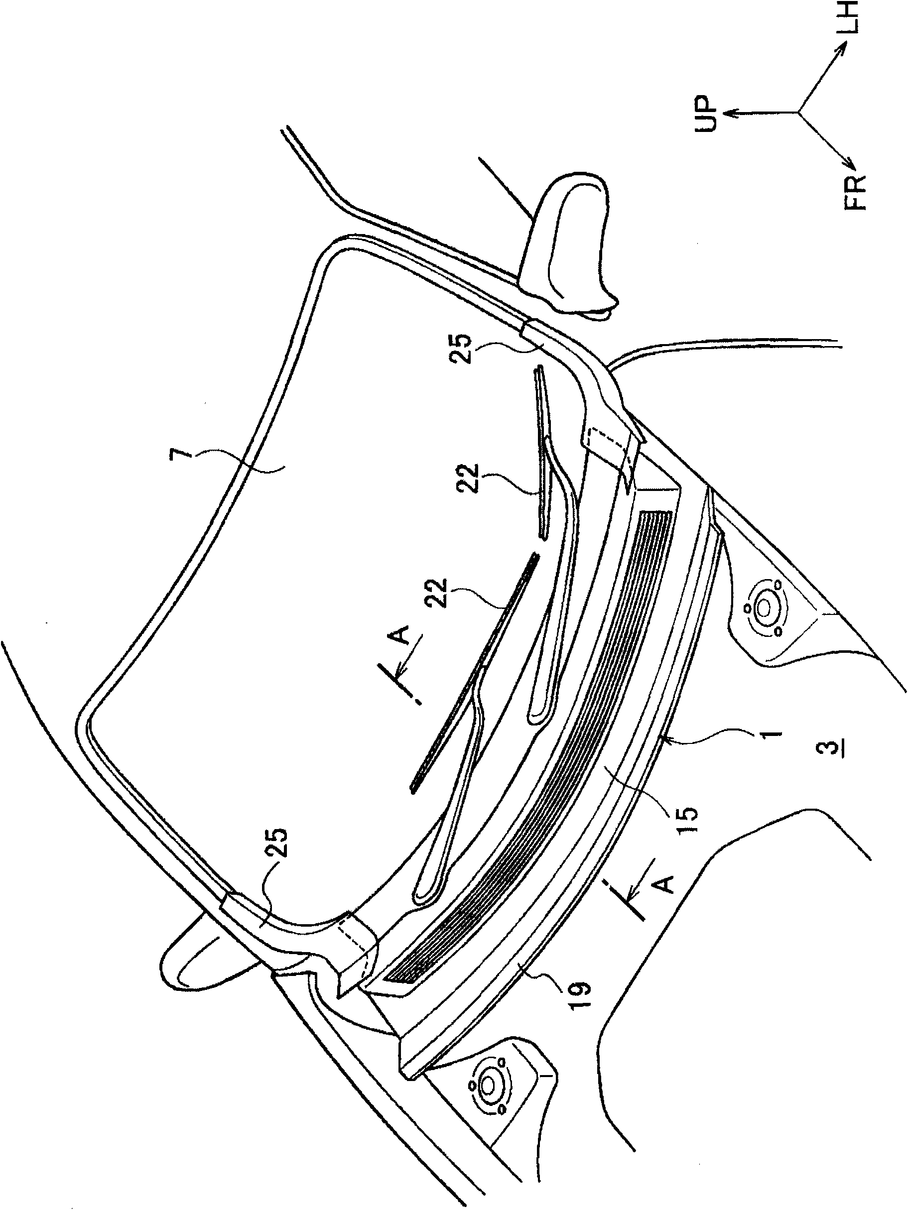
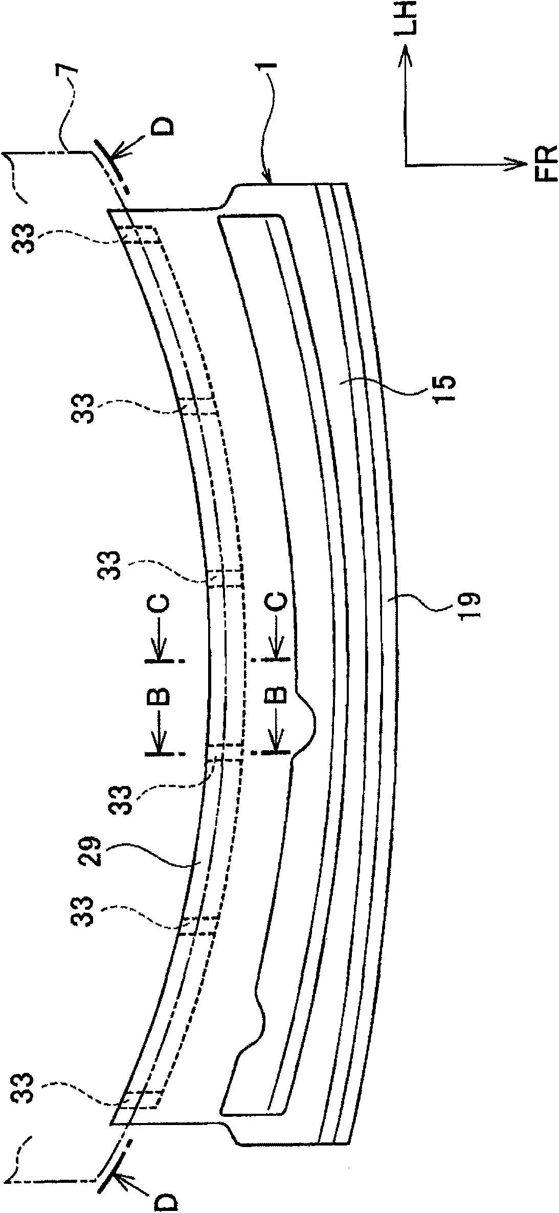
[0077] figure 1 yes figure 2 The A-A sectional view of FIG. 1 shows the installation structure of the cowl top according to the first embodiment of the present invention. In each drawing described below, the direction indicated by the arrow FR is the front of the vehicle, the direction indicated by the arrow UP is the upper side of the vehicle, and the direction indicated by the arrow LH is the left side of the vehicle.

[0078] The cowl top 1 is integrally formed of synthetic resin, is located between the cover 5 covering the upper opening of the engine room 3 and the front windshield panel 7, extends along the vehicle width direction, and covers the front windshield functioning as an air box. Surround the upper opening of upper panel 9. In the cowl top panel 9, the vehicle rear end portion 9a is attached to the partition plate 13 for separating the engine room 3 from the vehicle ...


PUM


Abstract

The invention provides a structure of mounting a cowl top cover, capable of preventing a back end portion of the integral cowl top cover formed by a synthetic resin mounted on a front windshield panel from deforming. The back end portion (27) of the cowl top cover (1) has a surface portion for covering the surface of the front windshield panel (7), clip portions (33) contacting with the back of the front windshield panel (7) and clipping the front windshield panel (7) between the clip portion and the surface portion, and thin plate portion (47) in a flat plate shape for connecting a plurality of clip portions (33) arranged along the vehicle direction.

Description

technical field [0001] The present invention relates to an attachment structure of a cowl top in which a rear end portion is attached to a lower end portion of a front windshield. Background technique [0002] In the prior art, as a structure for attaching the rear end portion of the cowl top to the lower end portion of the front windshield, the rear end portion of the cowl top is installed over the entire length of the vehicle width direction. The clamp or the fitting groove clamps the lower end of the front windshield panel almost the entire length in the vehicle width direction from the upper and lower sides. [0003] Patent Document 1: Japanese Patent No. 3919388 [0004] Patent Document 2: Japanese Patent Application Publication No. 1-144107 [0005] However, with regard to the mounting structure of the cowl top in the prior art as described above, when the cowl top is integrally molded with synthetic resin, due to one-time shrinkage during molding, the entire length ...

Claims


Application Information

Patent Timeline
Patent Type & Authority Applications(China)
IPC IPC(8): B62D25/14
CPCB60R13/07B62D25/24B62D25/081B60R13/06B60R13/04B62D25/08
Inventor 仓田武则原田裕史木村文彦寺田俊行村田贵裕藤泽学小林直树
Owner NIHON PLAST CO LTD
Learn More