
Window frame section integrally welded with single push-pull window frame

A frame profile and window frame technology, which is applied to windows/doors, leaf frames, door/window protection devices, etc., can solve the problems of poor heat insulation performance, low wind pressure resistance level, and not firmness, etc., to improve the overall Strength and wind pressure resistance level, improved sealing effect, low cost effect

Inactive Publication Date: 2010-07-28
李光
View PDF0 Cites 15 Cited by
  • Summary
  • Abstract
  • Description
  • Claims
  • Application Information

AI Technical Summary

Problems solved by technology

The single-track single-sliding window is not popular in the construction market for many reasons: the main reason is structural problems. First, the small mullion with the single sliding frame to fix the glass part is a screw-connected fixed structure, which is not only not strong but also not beautiful. , the wind pressure resistance level is also low, the processing process is inconvenient, and it is not easy to ensure the standard degree of installation
Locks should be installed at the position where the push-pull sash meets the small stile, it is easier to loosen the small stile under force, and it is difficult to repair, which may cause certain safety hazards in severe cases
Second, the push-pull frame and the fixed frame (that is, the upper bright frame or the lower bright frame) are split structures. The two frames are assembled together with screws through joint pipes to form a stack of profiles between the two frames and the joint pipes, which blocks light and is not beautiful. It is a waste of materials, and it is difficult to achieve tightness in the combined parts, and the heat insulation performance is not good
Since the height of the fixed position of the screw connection between the small stile and the frame body is on the same plane as the bottom of the slideway plate or at the upper and lower position, which is also the edge position of the fixed glass, the slideway plate is much higher than the installation position of the glass, resulting in Inconvenient to install glass
And because if the push-pull frame and the fixed frame are welded into an integral window frame, then the fixed frame position will have a protruding very large slideway plate, on the one hand it is inconvenient to install the glass, and on the other hand it is not beautiful
Therefore, people have not designed the single push-pull window frame profile that is integrally welded, and no one has designed the required mid-stile frame profile for the integrally welded frame.

Method used


Image

  • Window frame section integrally welded with single push-pull window frame
  • Window frame section integrally welded with single push-pull window frame
  • Window frame section integrally welded with single push-pull window frame

Examples


Embodiment 1

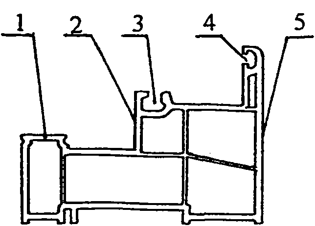
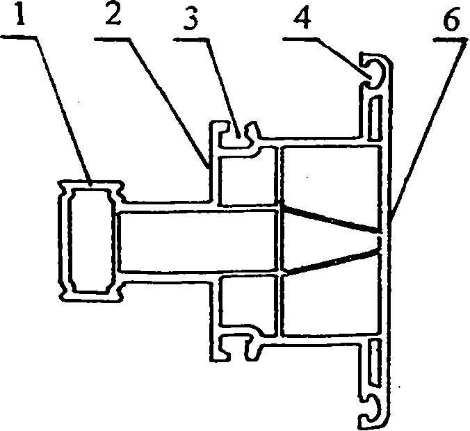
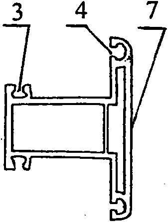
[0048] Embodiment 1, with reference to attached Figure 1-9, the single push-pull window frame is welded into an integrated window frame profile, and the profiles required to make the window frame 15 include frame profile 5, stile frame profile 6, small stile profile 7, and sealing strip 8. The processing process is to press the frame profile 5 according to the required Cut out the upper and lower frames and two vertical frames according to the required size, and cut out the V-shaped hole 13 for welding with the middle frame 6 at the required position and size of the two vertical frames 5, and cut out the V-shaped hole 13 for welding with the middle frame 6 at the required position and size of the lower frame 5. The small V-shaped hole 13-1 for the welding of the middle stile profile 7 is to cut the middle stile frame 6 into the shape of V tenon 14 at the two ends according to the required length, and cut out the welding with the small middle stile section 7 at the required pos...

Embodiment 2

[0049] Embodiment 2, with reference to attached Figure 3-5 , 10 to 15, which can realize the single push-pull window frame welded into an integrated window frame profile. The difference from Example 1 is that the profile structure of the frame 5 and the stile frame 6 is equipped with a heat insulation curtain 21 for connection. The curtain connection groove 20, the heat insulation curtain 21 is connected with the frame 5 and the stile frame 6 through the side heat insulation curtain connection groove 20, forming the overall heat insulation and sealing structure of the window frame 15.

Embodiment 3

[0050] Embodiment 3, with reference to attached Figure 3-4 , 16-22, can realize the single push-pull window frame welded into an integral window frame profile, and the difference from embodiment 1 is: the profile structure of the frame 5 and the stile frame 6 has a glideway 1-1, the window frame 15 The glide path 1-1 on the lower frame 5 directly does the glide path of the window sash 18. The glide path 1-1 of the middle stile frame 6 in the downward direction in the window frame 15 is assembled with the upper slide path heightening bar 11-1 to form the upper slide path of the window sash 18.


PUM


Abstract

The invention belongs to a window section for buildings, in particular to a window frame section integrally welded with a single push-pull window frame. The window frame section comprises a frame section (5), a muntin frame section (6), small-medium sections (7) and sealing strips (8), wherein the frame section (5) and the muntin frame section (6) are provided with section vertical surfaces (2) on which the small-medium sections (7) are welded; foundation slideways (1) are arranged on the frame section (5) and the muntin frame section (6) and are connected with a slideway heightening strip (11) and slideway sealing strips (12) in sequence; adhesive tapes (9) of the sealing strips and wood top ports (10) are arranged on the sealing strips (8); an adhesive tape port (4) is connected with screen window cloth (19) with the adhesive tapes; and the frame section (5) and the muntin frame section (6) are also provided with heat-insulating curtain connecting grooves (20). The window frame section integrally welded with the single push-pull window frame not only improves the integral strength and the grade for resisting wind pressure, but also improves the sealing effect and has low cost and favorable performance.

Description

technical field [0001] The invention belongs to a window profile for building, in particular to a single push-pull window frame welded into an integral window frame profile. Background technique [0002] At present, the windows used in buildings can be roughly divided into two types in terms of structure: the one is a sliding window (using double sliding rails and a double sliding fan structure), and the other is a casement window. The single-track single-sliding window is not popular in the construction market for many reasons: the main reason is structural problems. First, the small mullion with the single sliding frame to fix the glass part is a screw-connected fixed structure, which is not only not strong but also not beautiful. , the wind pressure resistance level is also low, the processing process is inconvenient, and it is not easy to ensure the standard degree of installation. Locks should be installed where the push-pull sash meets the small mullion, which can eas...

Claims


Application Information

Patent Timeline
Patent Type & Authority Applications(China)
IPC IPC(8): E06B3/26E06B3/46E06B9/264
Inventor 李光李思佳
Owner 李光
Learn More