
Measuring device for aligning with continuous casting crystallizer and measuring method thereof

A continuous casting crystallizer and measuring device technology, applied in the direction of measuring scales, measuring point marks, movable marks, etc., can solve problems such as heavy workload, hidden dangers of process safety, and long adjustment time, so as to prevent self-weight from falling and collect data Effective and time-saving effect of adjustment

Active Publication Date: 2010-07-28
WUHAN UNIV OF SCI & TECH
View PDF0 Cites 12 Cited by
  • Summary
  • Abstract
  • Description
  • Claims
  • Application Information

AI Technical Summary

Problems solved by technology

[0004] The centering device provided by VAI relies entirely on manual visual inspection, and judges whether it is centered by visually checking the bubble position of the alcohol level, and cannot display the distance between the foot roller and the first backup roller. Position deviation, and the deviation value between the two is very important for the continuous casting process, if it cannot be controlled within the specified range, it will cause safety hazards to the entire process
In addition, field engineers generally feel that the operation of this device is very inconvenient. Since the effective deviation value cannot be given, it is difficult to accurately install and position the crystallizer, so the adjustment time is long and the workload is heavy. These problems seriously hinder safe and efficient production. Work

Method used


Image

  • Measuring device for aligning with continuous casting crystallizer and measuring method thereof
  • Measuring device for aligning with continuous casting crystallizer and measuring method thereof
  • Measuring device for aligning with continuous casting crystallizer and measuring method thereof

Examples


Embodiment Construction

[0020] The present invention will be further described below in conjunction with accompanying drawing and specific embodiment:

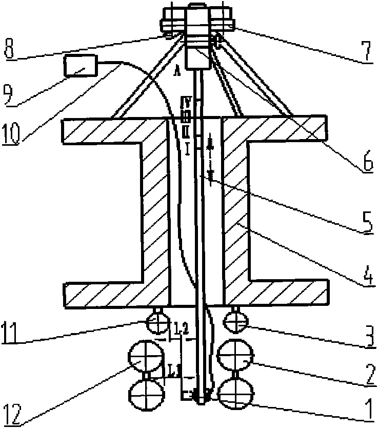
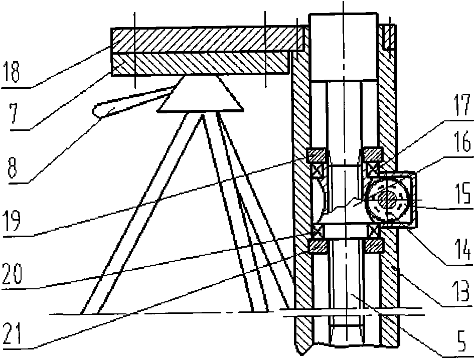
[0021] A continuous casting crystallizer centering measuring device and a measuring method thereof. The structure of the device is as figure 1 Shown: the device includes a sensor 1, a detection rod 5, a sliding device 6, a support adjustment frame 7 and a digital display table 9. The mounting plate 18 is fixed on the housing 13 in the sliding device 6, the lower plane of the mounting plate 18 is perpendicular to the center line of the housing 13, and the mounting plate 18 is fixed on the platform supporting the adjustment frame 7 by fastening bolts; It is installed in the housing 13 concentrically with the worm wheel 16 , and the sensor 1 is installed at the lower end of the detection rod 5 , and the sensor 1 is connected with the digital display meter 9 through the cable 10 .

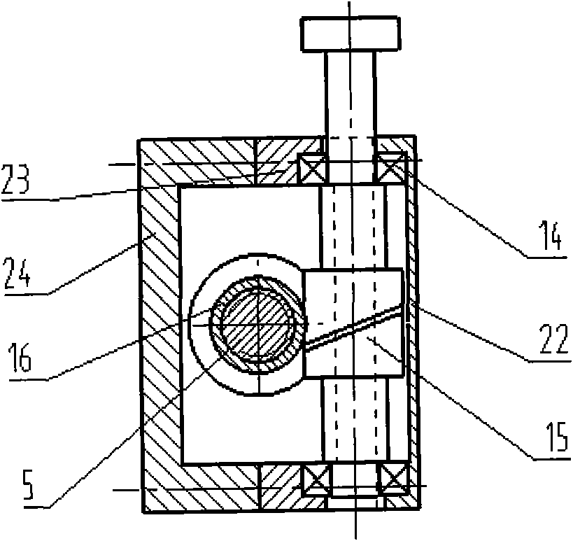
[0022] The structure of the sliding device 6 is as figure 2 , imag...


PUM


Abstract

The invention relates to a measuring device for aligning with a continuous casting crystallizer and a measuring method thereof. The technical scheme is that a mounting plate 18 of the device is fixed on a shell 13 of a sliding device 6; a lower plane of the mounting plate 18 is vertical to a center line of the shell 13; and the mounting plate 18 is fixed on a platform of a supporting adjusting bracket 7 through bolts. A detecting rod 5 is connected with a worm wheel 16 through threads; the detecting rod 5 and the worm wheel 16 are concentrically mounted in the shell 13; and a sensor 1 is arranged at the lower end of the detecting rod 5 and is connected with a digital display meter 9 through a cable 10. The measuring method of the device comprises the following steps: moving the detecting rod 5; measuring a distance L2 between an outside foot roll 11 and the sensor 1 through the sensor 1; measuring a distance L1 between an outside support roll 12 and the sensor 1; respectively taking minimum values of the distance L1 and the distance L2; calculating a pair arc delta L which is equal to the diffrence of L2 and L1 between the outside foot roll 11 and the outside support roll 12; and then adjusting the crystallizer to ensure that delta L is less than or equal to 0.3mm. The invention has the characteristics of rapid and accurate measurement.

Description

technical field [0001] The invention belongs to auxiliary equipment for continuous casting crystallizers, in particular to a continuous casting crystallizer centering measuring device and a measuring method thereof. Background technique [0002] The slab produced by continuous casting equipment is the raw material for rolling steel. The quality of the slab directly affects the quality of the final product. The mold is a very important part of the continuous casting machine. It is a forced water-cooled bottomless ingot mold. The "heart" of casting equipment. The installation accuracy of the continuous casting mold directly affects the quality of the slab. In particular, the arc alignment accuracy of the wide surface foot roll of the crystallizer and the first support roll (hereinafter referred to as the first support roll) on the upper part of the O sector in the bending section is an important factor affecting the surface quality of the slab, and once the arc deviation exce...

Claims


Application Information

Patent Timeline
Patent Type & Authority Applications(China)
IPC IPC(8): G01C15/06
Inventor 王兴东董元龙高全杰龙辽沙张留刚谢海华刘昀韩道旺
Owner WUHAN UNIV OF SCI & TECH
Learn More