Solar panel control structure and method

A technology for solar panels and control structures, applied in the direction of control using feedback, can solve problems such as the impact of tracking efficiency and the inability of the solar panel surface to face the sun light source accurately.

Inactive Publication Date: 2010-07-28
DELTA ELECTRONICS INC
View PDF0 Cites 12 Cited by
  • Summary
  • Abstract
  • Description
  • Claims
  • Application Information

AI Technical Summary

Problems solved by technology

[0003] However, if the light sensor is used to track the position of the sun, the tracking precision will be affected by the climate and the sensitivity of the light sensor. When the weather is b

Method used


Image

  • Solar panel control structure and method
  • Solar panel control structure and method
  • Solar panel control structure and method

Examples


Embodiment Construction

[0036] Preferred embodiments according to the present invention will be described below with reference to the relevant drawings, wherein the same elements will be described with the same reference numerals.

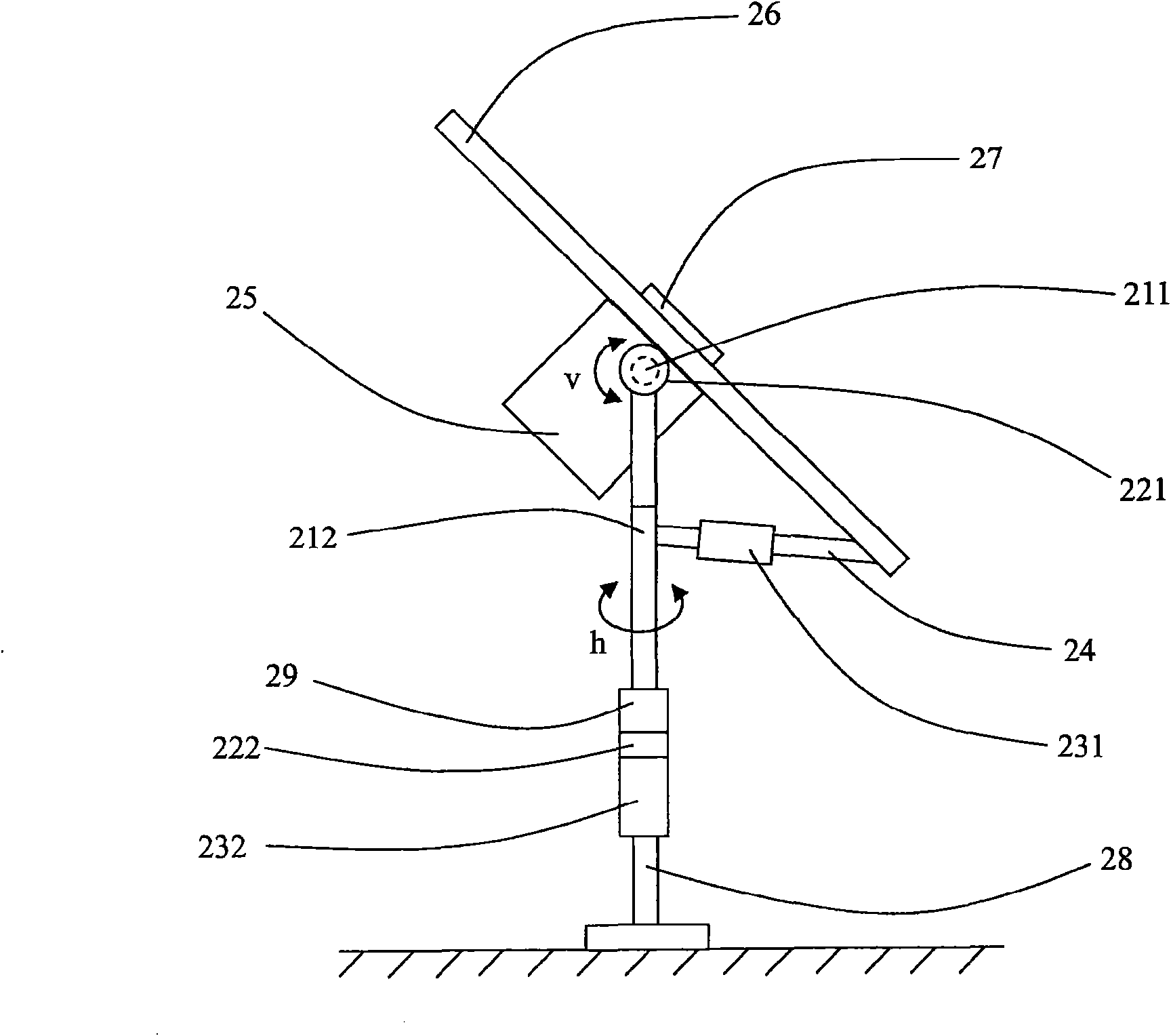
[0037] see figure 2, which shows a preferred embodiment of the solar panel control structure of the present invention, the light sensor 27 is used to sense the sun position when the solar panel control structure is initialized, so as to provide the controller 25 with the positioning of the solar panel 26 reference point, the The first rotating shaft 211 is used to control the vertical rotation v of the solar panel 26. The first encoder 221 is arranged on the first rotating shaft 211 to read the vertical angle of the solar panel 26. The connecting rod 24 is connected to the solar panel. One end of the panel 26, the first motor 231 is arranged on the connecting rod 24 to drive the connecting rod 24 to move, so that the connecting rod 24 drives the solar panel 26 to rotate ...


PUM


Abstract

The invention discloses a solar panel control structure and a solar panel control method. The solar panel control structure comprises a first rotating shaft, a first encoder, a connecting rod, a first motor and a controller, wherein the first rotating shaft is used for controlling vertical rotation of a solar panel; the first encoder is arranged on the first rotating shaft and is used for reading a first vertical angle of the first rotating shaft; the connecting rod is connected with one end of the solar panel; the first motor is arranged on the connecting rod and is used for driving the connecting rod to move so that the connecting rod drives the solar panel to rotate in the vertical direction; and the controller is connected with the first encoder and the first motor respectively and is used for controlling the first motor to rotate or not to rotate according to the vertical angle read by the first encoder.

Description

technical field [0001] The present invention relates to a solar panel control structure and method, in particular to a solar panel control structure that calculates the sun's position through solar trajectory data, and separates the motor from the encoder to precisely control the rotation angle of the solar panel to achieve the purpose of tracking the sun's trajectory and methods. Background technique [0002] Today, with the advancement of science and technology, people's living standards have improved, so the issue of environmental protection has been paid more and more attention. For the use of energy, it must mainly consider its economic benefits and pollution prevention. Especially today, the awareness of environmental protection around the world is increasing day by day. Therefore, the development It is urgent to use a low-pollution, pollution-free, high-economic-benefit energy to make up for the shortage of traditional energy. However, the incident angle of sunlight ...

Claims


Application Information

Patent Timeline
IPC IPC(8): G05D3/12
Inventor 张炫熙
Owner DELTA ELECTRONICS INC
Why Eureka
Try Eureka