Punching mold device capable of rotating a workpiece and punching method using same

A technology for stamping dies and rotating workpieces, applied in the stamping field, can solve the problems of cumulative error production efficiency, low positioning accuracy, inability to guarantee product quality, etc., and achieve the effect of improving production efficiency

Inactive Publication Date: 2019-12-20
QUANTA COMPUTER INC
View PDF7 Cites 5 Cited by
  • Summary
  • Abstract
  • Description
  • Claims
  • Application Information

AI Technical Summary

Problems solved by technology

Not only makes the processing procedure complicated, but also causes inconvenience to the operator
Furthermore, during production, the above-mentioned traditional division of labor needs to be replaced by other punching machines to carry out complex processing procedures, which not only has low positioning accuracy, but also tends to produce cumulative errors, resulting in low production efficiency and increased costs, and it is impossible to guarantee product quality.

Method used


Image

  • Punching mold device capable of rotating a workpiece and punching method using same
  • Punching mold device capable of rotating a workpiece and punching method using same
  • Punching mold device capable of rotating a workpiece and punching method using same

Examples


Embodiment Construction

[0081] Several embodiments of the present invention will be disclosed below with the accompanying drawings. For the sake of clarity, many practical details will be described together in the following description. It should be understood, however, that these practical details should not be used to limit the invention. That is to say, in the embodiment of the present invention, these practical details are unnecessary. In addition, for the sake of simplifying the drawings, some conventional structures and elements will be shown in a simple and schematic way in the drawings.

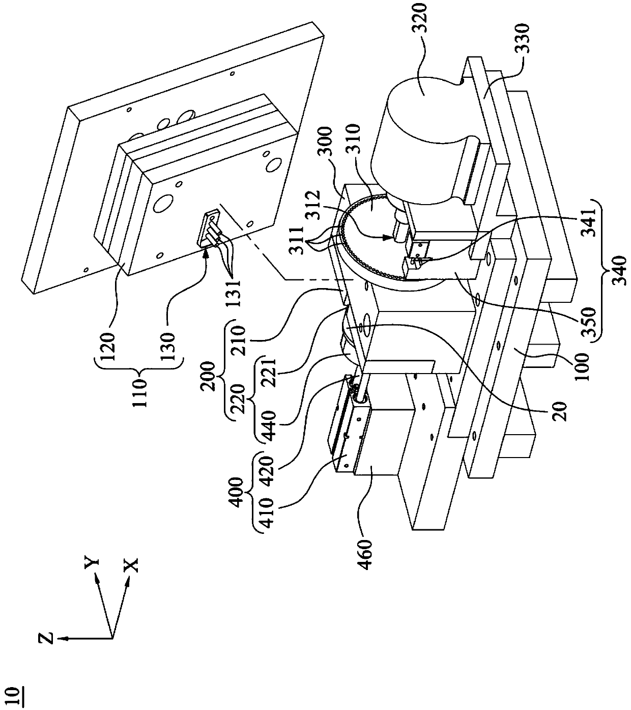
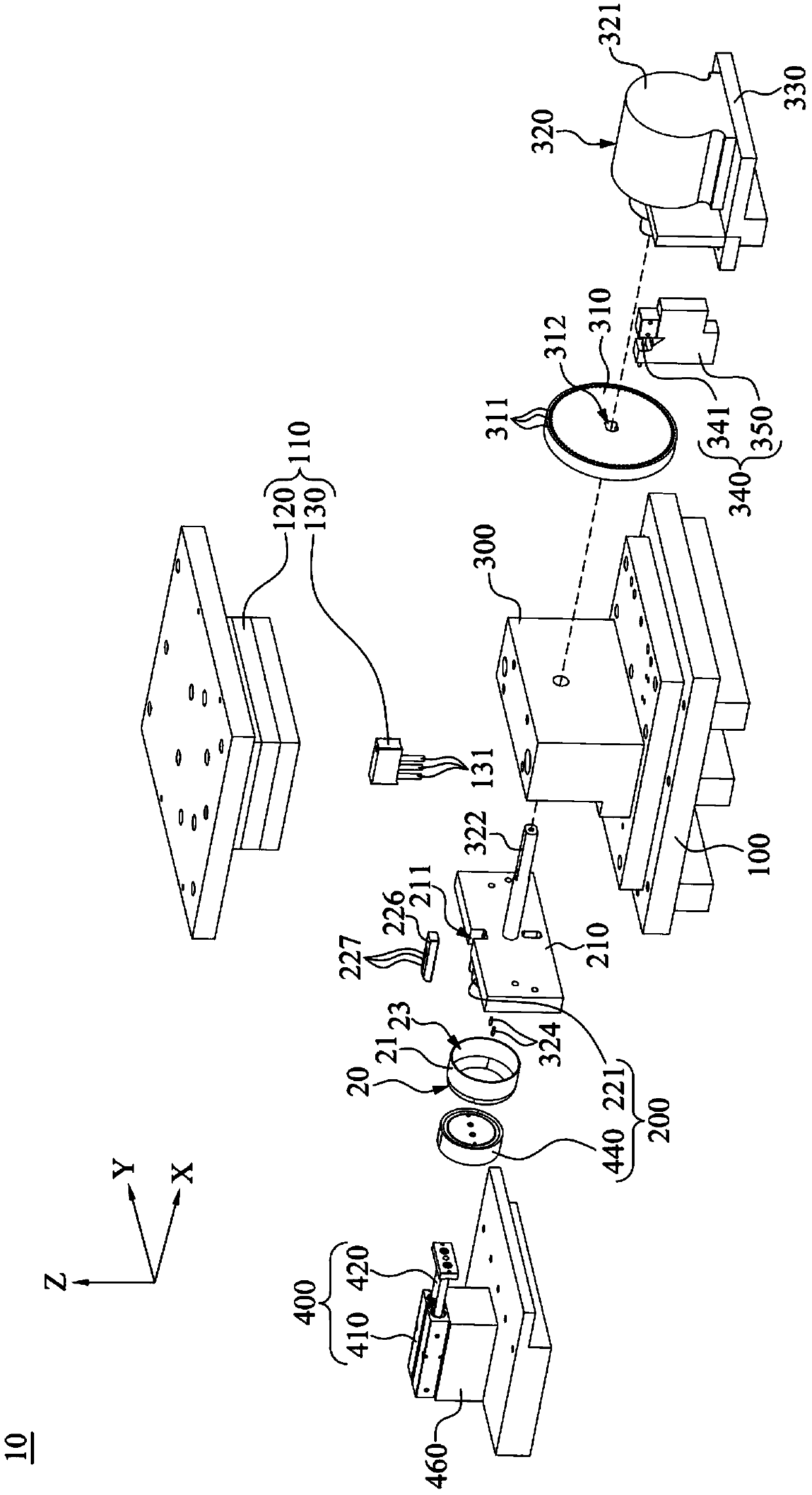
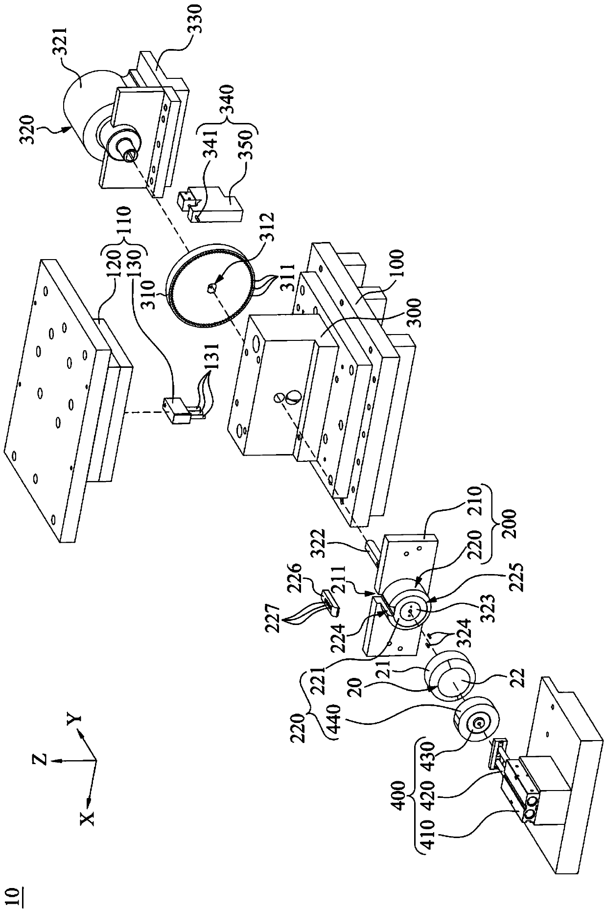
[0082] figure 1 A perspective view of a stamping die device 10 according to an embodiment of the present invention is shown. Figure 2A draw figure 1 An exploded view of the stamping die assembly 10. Figure 2B draw figure 1 Another perspective exploded view of the stamping die device 10 of . Such as figure 1 , Figure 2A and Figure 2B As shown, the stamping die device 10 includes a base 100, an up...


PUM


Abstract

The invention discloses a punching mold device capable of rotating a workpiece includes a punch module, a clamping portion, an indexing rotation disk, a servo motor, a position-fixing element and a central controlling portion. The clamping portion is used to clamp a workpiece. The indexing rotation disk is formed with a plurality of holes mutually surrounding a round contour. The indexing rotationdisk is coaxial to the workpiece. The servo motor is connected to the indexing rotation disk and the workpiece for synchronously rotating the indexing turntable and the workpiece. For example, a solenoid valve controls a positioning pin for forward / return motion to release / lock the indexing rotation disk. The central control unit is connected to the punch module and the indexing rotation disk forindexing and positioning for 360 degree punching.

Description

technical field [0001] The invention relates to a stamping die device, in particular to a stamping die device capable of rotating workpieces and a stamping method using the stamping die device. Background technique [0002] Stamping is to rely on presses and molds to apply external forces to workpieces (such as plates, strips, pipes and profiles, etc.) to cause deformation or separation (such as cutting, bending or punching grooves, etc.), so as to obtain the desired shape and size of the workpiece forming processing method. [0003] In the traditional stamping die, if it is necessary to stamp the circumferential surface of the cylindrical workpiece at 360 degrees in multiple angles and in different directions, it is necessary to disassemble various multi-stations to complete the required process. It not only makes the processing procedure complicated, but also causes inconvenience to the operators. Furthermore, during production, the above-mentioned traditional sub-statio...

Claims


Application Information

Patent Timeline
Patent Type & Authority Applications(China)
IPC IPC(8): B21D22/08B21D37/12
CPCB21D22/08B21D37/12B21D28/28B21D28/36B21D43/003B21D37/06B21D43/02
Inventor 林淑真
Owner QUANTA COMPUTER INC
Why Eureka
Try Eureka